[Back to Home Page]
www.RomanBlack.com
Cheap RF modules made easy!!
How to do serial comms using the cheap ebay RF 433/315 MHz modules
- 22nd April 2013.
These cheap RF modules usually come in a pair, with one transmitter and one receiver.
A pair can be bought on ebay for as cheap as $4, and even as cheap as $2
a pair if you buy 10 pairs.
Much of the information on the internet from people's projects
is sketchy and not very comprehensive.
I test these modules out, and show how to get good reliable serial comms
direct from USART -> USART, and I also show how to greatly speed up
the data rate and reliability by using an alternative bit encoding system.
Pinouts
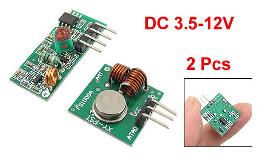
My cheap Ebay modules had this pinout;

Another popular brand (slightly more sophisticated) has this pinout;
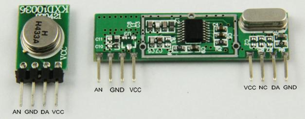
But all of these cheap type modules fit these 3 basic pin functions (plus antenna);
Transmitter;
Vcc (power+) 3v to 12v (works fine on 5v)
Gnd (ground-)
Data In (accepts logic level digital data, HI = transmitting carrier)
Receiver;
Vcc (power+) 5v (some may work on 3.3v)
Gnd (ground-)
Data Out (logic level digital data, HI = carrier present)
Data and transmission
This is very simple. When the transmitter data pin is LO, the transmitter is off,
and draws less than 1uA. (Mine drew 200 nA from the 5v supply when off).
When the transmitter data pin is HI, it is transmitting
solid 433 or 315 MHz carrier wave, and with a 5v supply my transmitter drew
about 12mA when transmitting continuous carrier.
The transmitter can be run from a higher voltage (like 12v) which increases
the transmitting power and range. My tests showed a 5v supply was plenty, even
for 20 metres range through multiple house walls. The transmitter is very crude,
and all it does is make an RF carrier wave whenever its data input is HI.
The receiver (when powered up) will crank up its gain untl it starts to
receive something. If no transmitter is working, the receiver will receive some static.
If a modulated carrier (a carrier wave which is turning on and off) is received,
the receiver will reduce its gain to remove lesser signals, and ideally
will then output the same modulated digital data as that which is controlling
the transmitter.
It's important to know that the receiver takes a bit of time to adjust its
gain, so any "packet" of data transmitted should start with a "preamble" before
the main data and the receiver will then have time to self-adjust its gain
before the important data starts.
Testing the RF modules!
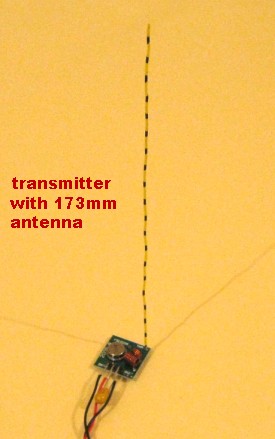
I ran both modules from separate regulated +5v DC supplies, and also
attached 173mm vertical "whip" style antennas.
(They were 433.92 MHz modules, so these were "1/4 wave" length antennas).
Range was tested from a few
metres open air, to about 20 metres through walls, and the range did not
seem to influence these tests much. So I assume these test results are
fairly typical of normal use.
Frequency and duty cycle testing
I used a digital frequency source with precise frequencies and exactly
50:50 duty cycle, this was used to modulate the transmitter Data IN pin.
I found that as the modulating frequency got higher the received duty
cycle was corrumpted, with the HI portion of the duty getting smaller;
Freq      Received HI Duty
50 Hz     49%
200 Hz    49%
500 Hz    48%
1 kHz     47%
2 kHz     43%
5 kHz     37%
10 kHz    26%
12 kHz    20-25%
16 kHz    bad!
This is very important for modulating the data, because if trying to
use a higher datarate the HI periods will become shorter and most
serial protocols like USART serial or manchester encoded serial will fail.
This is why these modules are normally only good for 1200 baud serial, or maybe
handle 2400 baud serial if everything is perfect (like high signal strength).
Above you can see scope results of the receiver output
from 3 different frequency tests, pasted into one picture.
All three of these signals was transmitted with exactly 50:50 duty
going into the transmitter Data IN pin.
At 1kHz the 50:50 duty of the original waveform into the transmitter
is ALMOST preserved, and comes out reliable at about 47% duty.
But the 5kHz and 10kHz are much worse! At 10kHz you can see the pulse widths are
very narrow and also noise/gain issues etc make each pulse a different width.
The receiver is struggling to capture these short (50uS) pulses.
Trying to fix the duty cycle at the transmitter
Next I adjusted the duty cycle at the transmitter, injecting a digital signal
still at 10 kHz, but now with 85% HI and 15% LO duty.
This had only a small effect! Below you can see the signal out of the receiver,
the received duty was improved slightly to about 36%, but remember this was
transmitted at 85% Hi duty!
Obviously it is a receiver issue, that is reducing pulse width at higher frequencies.
One thing that that WAS improved by transmitting with 10 kHz 85% duty (85uS HI pulses),
was that the received pulses were more uniform in width and looked more reliable.
That is good to know. :)
Simple comms, USART to USART
This was the next thing I tested. Knowing the modulated data was reasonably
preserved at 1 kHz, I tried a baudrate of 1200 baud direct from the PIC
USART TX pin to the Transmitter Data IN pin.
Plenty of people have done this on the internet with BASIC Stamps and
Arduinos etc, so this is the easiest way to get RF comms from a microcontroller
to another microcontroller, or from a microcontroller to a PC.
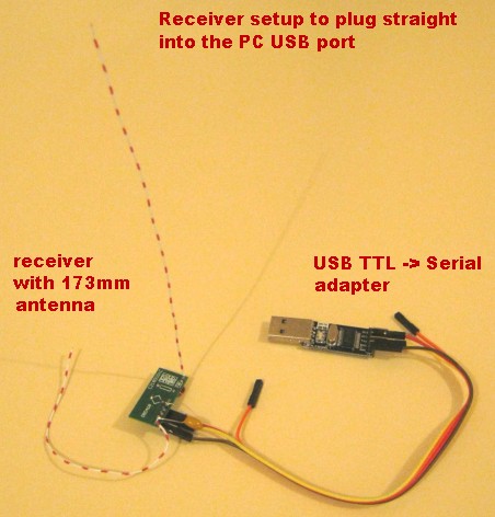
Above shows my simple setup for serial transmission from PIC, to be recieved with my PC.
The only change to the modules was adding a 10uF 25v tantalum cap across the
power pins (VCC to GND) on both modules.
The transmitter was connected direct to my
EasyPIC6 development PCB, and was driven from the PIC USART TX output pin.
The receiver was plugged direct into a cheap USB-TTL Serial adapter (also bought
from ebay for a couple of bucks). Three wires were connected; VCC, GND and RX.
This also powers the receiver module at 5v from the USB port, handy!
This setup is all that is required to send serial data from the PIC to a PC
(and be received in the PC using any serial program like Hyperterminal).
Testing serial data; PIC to PC
Set up for 1200 baud, the PIC USART takes about 8.3mS to send a byte.
I programmed the PIC to repeat a byte every 12mS, giving a small pause
(of approx 4 bits) between bytes sent.
Because the PIC USART data out is "typical TTL" type, the
default state is HI, so the transmitter is running between bytes (during the
extra 4 HI bits between each serial byte).
This extra transmit ON time helps to set the receiver gain.
Above (yellow trace) you can see the result at the receiver Data OUT pin.
The data is very nice and was decoded perfectly by the PC. I have manually
drawn some data on the scope wave so you can see the start and stop bits and
the 8 data bits (LSB first).
If you have worked with PIC USART serial data before this should look
very familiar, and what is coming out of the RF receiver here looks
identical to what came out of the PIC USART TX pin. Yay!
This byte was transmitted over and over, so the RF receiver had already
adjusted its gain to the optimal setting and reception was excellent. Becaue
of the 4 high (default) bits between each byte, total HI/LO duty of the data
was about 8:6 bits, or 57:43 duty cycle.
I moved the PIC transmitter, and tested different ranges, with the max range
about 20 metres and going through a few house walls. The result was very good
and showed that continuous transmission from a PIC to a PC (or to another PIC)
was effortless just directly using their USARTs and the two RF modules.
The "myth" of manchester encoding?
Some people say that these cheap RF modules should be used with manchester
encoding, an old style of data encoding that makes an equal amount of 1 and 0
bits (meant to balance the voltages used for the RF receiver gain averaging
circuit).
All my testing showed this was not necessary! Each byte sent every 12mS via USART
took approx 14 bits total repeat time, and the worst case examples were
these two bytes (shown below as 14 bit strings);
0x00 = 00000000011111
0xFF = 01111111111111
I really expected to have trouble with 0xFF as it is transmitting 13 bits HI
and only 1 bit LO, which is a duty of 13:1.
But it seems the RF receiver is adjusting the gain mainly on the strength
of the carrier (during the HI bits) and seems very tolerant of duty cycle!
As long as there is SOME content that is LO the receiver seems to handle
the data fine (at 1200 baud). Note! You cannot leave the data HI all the time,
because after about 50-100mS the gain will be reduced.
Your RF modules might be slightly different from mine, and if you are concerned
about keeping (roughly) the same number of HI and LO bits then one popular
method using the USART is to send each byte twice (but the second byte is inverted).
Obviously this will have half the data rate, but will keep a good average
of HI and LO bits, and it also allows some error checking as each byte
is repeated.
If doing that, I would still advise keeping those extra few stop bits
(transmitter ON bits) between each byte.
Limits of simple USART serial data
As I mentioned before, as frequency (baudrate) increases the receiver really
starts to have trouble maintaining the width of the HI bits, so the data
starts to corrupt.
I tested at 2400 baud, and found it worked OK but only if signal strength
was high and everything was perfect. Messing with shielding the antenna etc,
or anything that made the receiver adjust the gain up or down would start
to give data errors. Below shows the problem.
Compare the receiver output above, to the SAME BYTE shown in the 1200 baud
picture earlier. Both these scope shots at 4800 and 9600 baud were taken
with the signal strength perfect,
and with any signal or gain issues they were much worse. You can see
from the last two bits (1,0) how the 1 (HI) bit has been greatly reduced in
width (and has become dependent on signal strength).
The maximum baudrate for good reliability is about 1200 baud, but 2400 will
probably work ok if your signal is excellent.
The minimum baudrate I did not test fully, but frequency tests showed
the receiver made excellent looking data and duty even at 50Hz, so I would not
be surprised if a baudrate of 100 baud or even less would still work well.
Testing burst times and gain recovery
The receiver's gain auto-adjust works fine if the transmitting is constant. But in real
life the transmitter will probably transmit a small packet of data and then
turn off for a while. (Note! The legal band requirements for your area might also
say that the transmitter is not allowed to transmit continuously.)
I did some simple tests of transmitting a "burst" of carrier, modulated
at 1mS HI and 1mS LO (equivalent to 1000 baud data).
Above you can see the receiver data output, with a 100 mS OFF period,
followed by a 100 mS "burst" of modulated carrier 1mS Hi 1mS LO (ie 50 pulses).
Although the scope doesn't show the 50 pulses perfectly due to pixel
aliasing, the result was good when I later zoomed in.
The OFF period of 100mS was short enough for the gain to remain at
a reasonable level, and operation seems ok.
Above you can see the next test, again with the same 100mS of burst data,
but now with a longer OFF period of 150mS. You can see the last 50mS of
the OFF period was full of noise, because the gain had started to crank up.
Obviously that would cause a data problem.
I checked by zooming in, and it seemed the gain had recovered within about
2mS from the transmission start, so only the first pulse of the 50
transmitted pulses was corrupted. Apparently the gain stabilises pretty
quickly once a real transmission starts.
Below is another test, this time with very short bursts and long pauses;
Above the scope shot looks messy, but what it shows is just 20mS transmitted
bursts (10 pulses each) with a 150mS OFF period between each burst.
The problem is that shortly after each burst (about 20mS after) the gain
cranks up and then the receiver is picking up noise. (The noise signal
is close to 50Hz so is likely coming from my big fluoro lights in my
workshop.)
In all three tests above it looks like the receiver is fine for a short
while after a data burst, for a time period about as long as the data burst
was.
Time before data comes good?
All tests were similar in that once transmitting starts, the data was good
within a couple of mS. In my case that was by about the 2nd data pulse.
Even after a long period of no transmission where the receiver gain has
reached max (which can occur as quickly as 100mS if the last burst was small)
the receiver stabilises within a couple of mS once transmission starts
again.
So it looks as though even a single setup byte ("preamble" byte) will be
enough to let the receiver lock in to the signal and good data bytes can
follow.
You may want to use more preamble bytes, for safety. I did check under
different signal conditions and my receiver always locked in very quickly.
You may have a different type of receiver. Mine is a very cheap simple
analogue type, which only has 2 transistors and a LM358 opamp.
(See the photo at the very top of this page). Some receivers
look a bit more complex, so whether that makes them lock in quicker or
slower will need to be tested. :)
"Preamble" tips for simple USART apps
If you are going to use the direct USART -> USART system then it is important
to use a "preamble" system to get the receiver gain sorted before the
actual data bytes start.
It is good to send 2 or 3 preamble bytes first, then the data packet.
Synchronising bytes
As the first byte or two might be corrupted, the receiving USART might
synchronise badly, and then all following bytes would not be correctly
decoded.
A common way to get around this is to keep the first few bytes very short
(with minimal 0 bits), and combined with the few extra spare bits between
each byte this allows the maximum time to re-synchronise on each
following byte;
Above shows a good way to do a 3-byte USART preamble.
To send a packet of data, the USART is turned on (output goes HI)
and starts the transmitter, then there is a 12mS pause.
That solid 12mS of carrier transmission should be enough for the receiver
to set its rough gain so the following preamble bytes can sync.
After that, each byte is transmitted every 12mS. The 3 preamble bytes
are 0xF8, 0xF8, 0xFA, all of which have very short LO times (see the scope
picture above).
This should allow plenty of time for the receiver to fine tune its gain
and the long HI periods between bytes ensure that the USART gets a
good byte sync.
After the 3 preamble bytes, there can be any number of data bytes,
each byte is sent every 12mS.
In this case I just sent 3 ascii data bytes; 'A', 'B', 'C'.
After the last data byte is sent the USART is turned off (which turns
the transmitter off).
Decoding the USART data
The main problem with the USART receiver will be the static the RF receiver
picks up when the transmitter is not transmitting.
The static will cause the receiving USART to record lots of garbage bytes.
The easy way around this is to keep clearing the USART of all garbage bytes
until the byte pair; 0xF8, 0xFA are received.
Those two bytes are the last two bytes of the
preamble, and should be reliable as the receiver has had time by then to
fix its gain. After those two bytes, a packet of data bytes will come out of
the USART automatically.
If you want more safety, just send a longer preamble;
0xF8, 0xF8, 0xF8, 0xF8, 0xF8, 0xFA
And look for a 4-byte set;
0xF8, 0xF8, 0xF8, 0xFA
to signal that valid data will come next.
Getting much higher datarates by NOT using the USART!
Using a simple USART solution is very easy, but limits baudrate to about
1200 baud. Some receivers also might need you to send two of each byte,
the second byte inverted to keep 1 and 0 bits roughly even.
That limits the number of bytes sent to about 43 bytes per second,
in continuous transmission. It will be slower still in burst
transmissions as some time is needed for preambles etc.
A solution?
The problem at higher baudrates than 1200 is the receiver makes the HI
bits smaller in width, and their width is further affected by signal
strength and noise etc.
Similar problems exist in InfraRed remotes, and they get around this
by using a pulse period encoded system, where it does not matter how wide
any pulse is.
I threw together a very similar system to the one used in InfraRed remotes,
and tried it with the RF modules. :)
Above shows how I transmitted a byte. (Data at the transmitter Data IN pin)
Based on my earlier testing at 10kHz transmission and pulse widths, I made
the HI pulses of a fixed width of 80uS. This 80uS width was enough for
the receiver to lock on to, even with low signal strengths.
The protocol is very simple;
pause between bytes (Start pulse) = 250 uS
0 bit = 100 uS
1 bit = 150 uS
(HI pulse width always 80uS. Data is sent MSB first)
As all bits contain some HI and some LO component, there is no need
to send data bytes twice with the second byte inverted. With this
system there is plenty of HI and LO content in a continuous transmission
to keep the receiver happy.
Most importantly, it does not matter how wide the received HI pulses are!
These pulses are wide enough for the receiver to capture, and even if
signal conditions change and the pulses change width a bit, that will not
matter. The width of HI pulses is not measured, only the time from pulse to pulse.
Above shows the system works! This is data coming out of the receiver.
You can see the HI pulse widths vary a bit, but all pulses are represented
reliably (even when I changed signal strength).
Most importantly, the critical decoding is measured from the END of each
HI pulse (the \ edge). This is the most reliable edge of the HI pulse.
The reason it is the most reliable edge is because the receiver adjusts
gain during the HI pulse, so at the time the HI pulse ends the receiver
gain is good, and it reproduces the end of the transmitted pulse quite
accurately..
You can see how well this works by the timings shown above, measured from
each pulse \ edge. All the 0 bits are the same size (100uS)
and the 1 bits are all the same size (150uS).
Software decoding can detect byte sync very easily if any pulse is over 200uS
(detects the "pause between bytes" or "start pulse");
>200uS = start pulse
Then 0 and 1 bits are 100uS and 150uS,
so decoding the 8 bits is as simple as comparing to the mid value (125uS);
<125uS = 0 bit
>125uS = 1 bit
Benefits of this system
* Much higher datarate than USART examples
* Much higher data reliability than USART examples (even at higher baudrates)
* No need to repeat inverted bytes (already has good enough HI/LO balance)
* Seems quite immune to signal strength issues
* Extremely reliable byte-sync detection
* Transmission is normally OFF (energy efficiency)
* Fixed width pulses of transmitter ON (suits higher transmitting power)
* Transmitting and receiving devices do not require a USART (cheap small PICs?)
So it works great! How fast is it?
With the simple USART system aiming for excellent reliability the highest
baudrate I could get was 1200, with 1 byte transmitted every 12mS.
That is a speed of 83 bytes per second. If you decided to transmit two of
each byte (second byte inverted) that would come down to 42 bytes per second.
With the new pulse period protocol it had excellent reliability with
the timings shown in the scope images above. The speed depends on whether
the data contains more 0's or 1's, but worst case (0xFF) would give 689 bytes per second,
and an average speed would be around 800 bytes per second! And there is no
longer any need to transmit two of each byte to balance the HI/LO bias.
Source code for pulse period protocol
Here is my Mikro C source code function to transmit a byte;
//=============================================================================
//   SEND_RF_BYTE
//=============================================================================
void send_rf_byte(unsigned char txdat)
{
  //-------------------------------------------------------
  // This is a pulse period encoded system to send a byte to RF module.
  // Bits are sent MSB first. Each byte sends 9 pulses (makes 8 periods).
  // Timing;
  //   HI pulse width; always 80uS
  //   0 bit, LO width; 20uS (total 0 bit pulse period 100uS)
  //   1 bit, LO width; 70uS (total 1 bit pulse period 150uS)
  //   space between bytes, LO width; 170uS (total space period 250uS)
  // (timings tested with 20MHz xtal PIC 18F, no pll)
  //-------------------------------------------------------
  unsigned char tbit;

  // make 250uS start bit first
  Delay_uS(170);      // 170uS LO
  LATC.F6 = 1;
  Delay_uS(80-1);     // 80uS HI
  LATC.F6 = 0;

  // now loop and send 8 bits
  for(tbit=0; tbit<8; tbit++)
  {
    Delay_uS(20-1);             // default 0 bit LO period is 20uS
    if(txdat.F7) Delay_uS(50);  // increase the LO period if is a 1 bit!
    LATC.F6 = 1;
    Delay_uS(80-1);             // 80uS HI pulse
    LATC.F6 = 0;
    txdat <<= 1;                // roll data byte left to get next bit
  }
}
//-----------------------------------------------------------------------------
System to receive a byte;
This is a little bit more complex and depends how you want to handle
detecting a preamble and packet size. As a general system to receive a
10 byte packet, it could be done like this;
1. must first detect a valid start pulse >200uS, then can try to record 8 bits
2. record 8 bits. If any is >200uS, is some error (static) so start again
3. if we had a good start pulse, and 8 good bits, record it as a received byte!
4. after a full packet of 10 contiguous bytes is received, all done!
Basically this C function below will wait until 10 contiguous (sequential)
"good" bytes are received. A "good" byte must have a good start bit
followed by 8 good data bits. If static or noise is received the function
will just keep resetting itself until 10 good contiguous bytes occur.
unsigned char rxdat[10];  // (global var) holds received RF bytes

//=============================================================================
//   RECEIVE_RF_PACKET
//=============================================================================
void receive_rf_packet(void)
{
  //-------------------------------------------------------
  // This function receives an RF packet of bytes in my pulse period
  // encoded format. The packet must have 10 valid contiguous bytes
  // or the function will not exit. There is no timeout feature, but could be added.
  // global variable; unsigned char rxdat[10] holds the 10 byte result.
  // Note! TMR0 is running at 500kHz, so 200uS = 100 TMR0 ticks
  //-------------------------------------------------------
  unsigned char rrp_data;
  unsigned char rrp_period;
  unsigned char rrp_bits;
  unsigned char rrp_bytes;

  rrp_bytes = 0;
  while(rrp_bytes < 10)   // loop until it has received 10 contiguous RF bytes
  {
    //-----------------------------------------
    // wait for a start pulse >200uS
    while(1)
    {
      while(!PORTC.F7) continue;    // wait for input / edge
      while(PORTC.F7) continue;     // wait for input \ edge
      rrp_period = TMR0L;           // grab the pulse period!
      TMR0L = 0;                    // and ready to record next period
      if(rrp_period < 100) rrp_bytes = 0;   // clear bytecount if still receiving noise
      else break;                   // exit if pulse was >200uS
    }

    //-----------------------------------------
    // now we had a start pulse, record 8 bits
    rrp_bits = 8;
    while(rrp_bits)
    {
      while(!PORTC.F7) continue;    // wait for input / edge
      while(PORTC.F7) continue;     // wait for input \ edge
      rrp_period = TMR0L;           // grab the pulse period!
      TMR0L = 0;                    // and ready to record next period

      if(rrp_period >= 100) break;  // if >=200uS, is unexpected start pulse!

      if(rrp_period < 61) rrp_data.F0 = 0;    // 61 = 122uS
      else                rrp_data.F0 = 1;
      rrp_data = (rrp_data << 1);   // save the good bit into rrp_data
      rrp_bits--;                   // and record 1 more good bit done
    }

    //-----------------------------------------
    // gets to here after 8 good bits OR after an error (unexpected start pulse)
    if(rrp_bits)      // if error
    {
      rrp_bytes = 0;  // reset bytes, must run from start of a new packet again!
    }
    else              // else 8 good bits were received
    {
      rxdat[rrp_bytes] = rrp_data;  // so save the received byte into array
      rrp_bytes++;                  // record another good byte was saved
    }
  }
}
//-----------------------------------------------------------------------------
Note! Each received byte must consist of;
1 valid start pulse (period between 200-500 uS)
8 valid data bits (each bit period is <200 uS)
Preamble for pulse period protocol?
After writing and testing the transmit and receive packet functions,
it became obvious the preamble could be very simple.
All that was needed for a "preamble" was to send a handful of start pulses
(each has a period of 250uS),
these pulses keep resetting (and re-synchronising!) the packet receive function
until the first byte starts.
(The "first byte" wll be a start pulse followed by 8 good data bit pulses).
There you go! That's all you need to get good reliable one way data comms
at 600-800+ bytes per second from very cheap RF modules. Have fun.
- end -
[Back to Home Page]