[Back to Home Page]
www.RomanBlack.com
$40 DIY VGA microscope for SMD work
Making a standalone SMD microscope from a spare VGA monitor!
Roman Black - 15th Jan 2013
An SMD microscope for under $40?
OK, firstly I'll confess I already had the 15" flatscreen VGA computer
monitor. It was given to me broken, (with no backlight) and replacing the
caps in it's PSU got the monitor working.
The monitor had beek kicking around my workshop for a couple of years,
and in the back of my mind I had the idea of keeping it to make a
"standalone" big screen microscope for SMD electronics work.
I know you can buy cheap crappy USB "microscopes" for about $30-$40 like this
type;

However these have the disadvantage of needing a PC, and it was important
to me to have a fully self-contained "standalone" SMD microscope that
could be moved from desk to desk, between workshop rooms etc.
Also, the cheap USB microscopes have the wrong magnification, I wanted
something about 8:1 or 10:1 magnification like a proper commercial SMD
inspection microscope (which costs $500). :)
How it works
Basically it requires just connecting 4 things together;
1. A cheap ebay PAL/NTSC composite video camera.
2. A PAL/NTSC to VGA converter box.
3. Some high brightness white LEDs.
4. A spare VGA computer monitor.
For a couple of years I kept an eye out for a camera that had a VGA output,
which would have made an easy microscope with my spare VGA monitor.
However these are almost impossible to find, all the cheap common
cameras are composite video output.
Then recently on ebay I saw these gizmos;
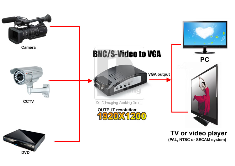
Available from lots of resellers for prices ranging from about $14
to $21. I paid about $16 and shipping was free.
The converter is pretty smart, it has buttons and menu to select
different screen resolutions, and it had all common resolutions used
in computer monitors (including my monitor's 1024 x 768). It also came
complete with a tiny SMPS regulated +5v plugpack, which came in
very handy!
Choosing a camera
This was easy, I just picked a cheap ebay camera at random. I chose
a dome-style security camera with built in IR night-lighting, for $14;
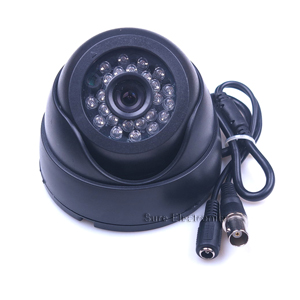
Like the VGA converter gizmo, these "composite video cameras"
are available cheap from heaps of different sellers, and I chose
PAL format because I'm in Australia (US residents would choose
NTSC version).
Of course if the camera was no good for a microscope then I could
always use on my home security stuff as it can plug into any TV.
I also knew from experience the lenses are adjustable for focus,
so it should be possible to make it work directly as a microscope
or "tune it" to suit an additional magnifying lens.
Modifying the camera
First I checked the camera worked ok with the VGA converter gizmo and
the VGA monitor. It all plugged together and seemed to work ok, but the
camera colour sucked. This was mainly due to the camera having a built
in InfraRed lighting system, which adjusted it's IR illumination
according to room light.
With a few twists the camera all popped open. The camera module PCB,
and IR PCB were separate (excellent) and also on separate plug wires.
Both ran from 12v DC. I removed the camera module itself and did some
tests. :)
With no IR illumination now the camera gave decent colour reproduction,
provided the target was lit with white light. White LEDs seemed to work
ok too, which was a useful test.
Checking the camera module PCB showed a 78L05 SMD regulator, converting
the incoming 12v DC to +5v DC to run the camera. This was also excellent
as I wanted to use 5v power.
I unsoldered the 78L05 SMD regulator (bottom left of PCB)
and just connected a red and black wire direct to the cap which
was the 5v rail;
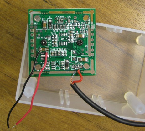
I also unsoldered the white 3-pin connector as it would have been in the
way, and instead soldered on a fine piece of black coax, for the composite
video output. A quick test showed the camera still worked fine running
from a 5v supply and the new coax cable was connected right.
The InfraRed illuminator and Dome housing was thrown in my junk box
for later use. It has a LDR photodetector, 24 high brightness near-InfraRed LEDs
and a few transistors and runs from 12v, it might be useful for something.
Collecting all the parts
At the same time I was modding the camera I dug out two little plastic
project boxes. These are nromally about $3 - $4 each, I bought a few
together on special so they were cheaper. They are a standard small
hobby size 80 x 55 x 30 mm.
I worked out where I was going to mount the boxes on the monitor and
drilled some holes for the wires;
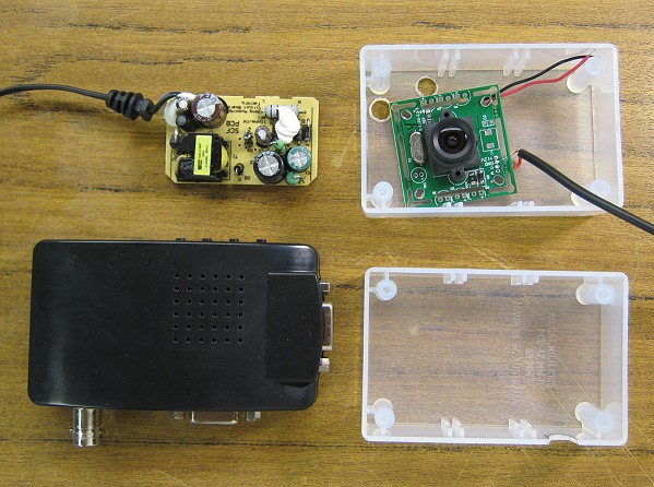
The small PCB is the guts from the free 5v plugpack that came with the
VGA converter gizmo. It runs from 100-240v AC, and makes regulated
+5v DC @ 1 amp. That should be plenty!
How to mount the camera?
I decided on a "Borg hive" construction technique of just gluing
everything together with hot melt glue. This should be reliable enough
and still gives the option of breaking the glue off and re-using or
modifying parts later. Who am I to argue with the wisdom of Borgs? :)
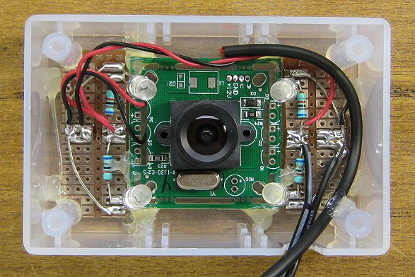
The camera module was "assimilated" into the plastic box with a few spots
of hot glue. I cut two small chunks of stripboard and soldered on 4
high brightness white LEDs. These were sold as 20000 mCd LEDs and are
very bright, but a bit too directional for my liking. I chose 4 resistors
that gave about 26 mA current in each LED.
Total power usage (at 5v) is about 124 mA; 20 mA for the camera plus the 4 LEDs.
Testing showed the LEDs were a bit too bright, and a bit hard to aim
but I bent their legs and pointed them at the target, which would be
at the focal point.
Focusing the camera
This was so easy it was a joke. The camera lens was on a fine thread,
with a grub screw. The grub screw was loosened and the camera lens
screwed out a bit, which soon gave perfect focus at about 30 mm
(distance between target and lens), and the desired magnification!
No additional lens would be needed.
This close focus gives a slight "fish eye" distortion (see the photos)
but that does not bother me at all. It will do the job good enough!
Final assembly!
The hardest part was getting that little plugpack PCB out of the free
plugpack. The casing of the thing was ultrasonic welded together, and
I actually had to hacksaw all the way around the casing the break it
open!
But even though it resisted, all Borg assemblers know "resistance is futile"
and the little yellow PCB was soon assimilated into the plastic box,
which was itself assimilated into the monitor;
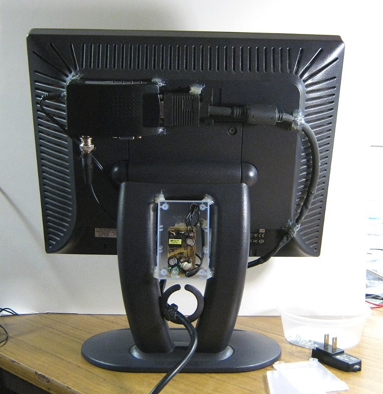
Warning! Borg construction technology!
The VGA converter gizmo
was hot glued onto the back of the monitor with a 5mm airgap between it
and the monitor. All its plugs and buttons are accessible, however once
it was set to 1024 x 768 to suit my monitor it memorised the setting and
I have not needed to touch a button since.
The VGA-VGA cable was hand soldered from a couple of
old PC monitor cables joined at the right length, because all my new VGA
cables are 1 metre long. It was annoying joining the 10 or more little
wires but I had worked with VGA before and knew the pinouts etc.
The small 5v plugpack PCB was powered from a tap I made (safely!) on
the 240v AC mains lead. This was done to make the whole thing into
a standalone "appliance" with just one power lead. It is important that
I can just pick it up and move it from workshop to workshop.
Note! I did put the cover on that plastic box, live parts are inside.
If you have not used hot glue like this before, it is actually pretty
strong! An important trick is to wipe down all surfaces with alcohol
to clean them, then the hot glue will be permanent enough to be relied
on for many years.
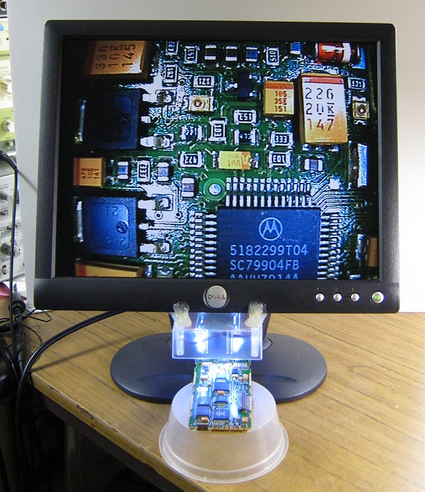
Testing
As you can see below the camera box was just glued under the front of the
monitor, there is a lot of overhang on this monitor so it can inspect
PCBs up to about 120mm in from the edge (or 240mm wide in total).
There is no system yet to
position the height of the object being inspected, but fortunately
the camera focus is quite forgiving so it's easy to hold the object
at the right height or just stick a book or box under it;
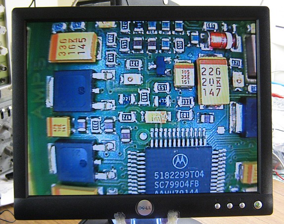
The monitor screen above looks dark and badly lit, but in real life
it looks pretty good. I think my Canon camera (taking the photo) messed
up the brightness and contrast because the of the super powered white
LEDs in the view.
However there are a couple of real issues; There is a "fish eye"
problem, which I will just live with. Actually I didn't really notice
it when using the miscroscope and moving the board around as you tend
to look more near the centre of the screen, but it looks bad in the photo.
The issue I need to fix is the specularity of the LED lighting.
There are an obvious 4 "spots" of bright light on the target, and they
are too bright, enough to get some "white out" in the image.
When this photo was taken there were no diffusers, so the next step
was to make a diffuser to turn the 4 LED light beams into more of a
diffuse "all over" glow.
Nostalgia! The PCB being inspected is an old Motorola analogue
cellphone from about 1989.
Magnification is fixed at 9:1 (by my choice!) and
the resistors etc are 0805 parts to give you an idea of the sizes.
Added a diffuser
I put the translucent plastic cover on the camera box, after drilling
a centre hole for the camera. To make it diffuse better I scratched a
heap of lines on the cover with a sharp scriber. This reduced and spread
the light a bit;
As you can see the light is much better distributed and overall
contrast is more even. The "white out" problem is practially gone.
There are still four bright spots, which is
actually handy when moving the target PCB around to shine off the top
of parts and read the tiny laser marked print which has no colouring it's
more like indented print.
Again my Canon camera does not really catch the quality of the screen
and it has washed out a bit in the photo.
But overall I'm pretty happy with the viewing quality, it is quite pleasant
to inspect a PCB, compared to the old glass magnifiers I normally use.
I will experiment with lighting and diffusers later and it should come up
better still after some fine tuning.
But for now, I'm delighted with my self contained SMD inspection microscope
for total cost under $40 (not includng monitor).
:)
- end -
[Back to Home Page]