[Back to Home Page]
www.RomanBlack.com
My homemade "Gainclone" hifi amplifier
I used an old power amp case and rebuilt into a world-class hifi amp
for my home studio.
Roman Black - Jan 2009 - web 05th Mar 2009.
What is it?
This is a hifi audio amplifier I built based on LM3876 audio amplifier
chips - which have a web following known as "Gainclone" amplifiers.
I built this amp to be my main stereo amp in my home recording studio,
and it is optimised for very good sound quality and (hopefully)
reliability. :)
This page includes build info, pictures and schematics if you want to
build a similar amp.
Features
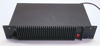
Beefy 19inch rack style case...
Very sexy! I bought the original amp off ebay a couple of years back.
Cheap, because it was originally an Australian kit-amp (ETI5000 ?)
and poor design (unstable overpowered mosfet amps) coupled with
sadistic P.A. use and sloppy home construction caused one amp to blow,
burn badly, was then repaired by a visually impaired orangutan
and subsequently blew up again...
These 1980's kit amps came with a custom cast aluminium front panel
heatsink, and I had always wanted one. I love that "industrial" persona
of chunky 19inch rack equipment, and for my home studio it would fit
nice with my 19inch effects units etc.
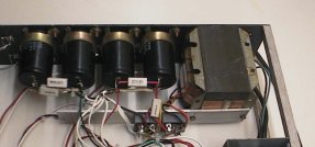
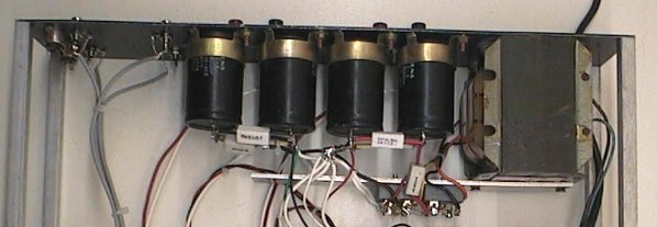
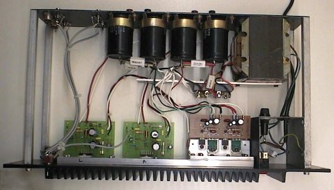
Massive primary power supply!
The original amp had 2 beefy transformers and 4 good power 8000uF
capacitors. I think the original amp was dual 150w, ie a big
P.A. amp for bands. Anyway I removed one transformer (which itself
was worth close to what I paid for the blown amp) and used one
transformer only. Which is still overkill. :)
Dual mono "Gainclone" amplifier modules.
I used 2 amp modules (ie stereo) but arranged as dual mono so each has
fully independent wiring from input to speaker. These amps use the
National Semiconductor LM3876 amplifier chip which is gaining (hehe)
a cult following for stunning sound quality. I also modded the kit
modules to further improve to my own specs.
Front panel aluminium heatsink.
The original amps front panel heatsink was a little scratched from
what looked like years of hard P.A. use but cleaned up pretty good.
It is powdercoated black, and since the panel rear is slightly ripply
from the casting and powdercoating I improved the heatsink by adding
a 40mm x 10mm aluminium bar which bolts firmly to the rear of the
front panel heatsink.
This gave 3 benefits; improving total sink mass, providing a very
flat smooth surface to bolt the amp chips to, and a much larger
contact area to transmit heat through to the front sink.
Secondary power supply regulator!
This is a feature found in only some of the highest end audio amps costing
many thousands of dollars and in some eccentric home built amplifiers.
This was also one of my reasons for choosing the LM3876 modules,
I was forced to use a secondary regulator as the primary power supply
delivered +/- 53vdc and most of the amp modules I was considering
required 30 to 38v. Some internet surfing provided lots of links to
superb performance home built amps using regulated power supplies
and LM3876 amplifiers.
So the basic design spec for my studio amp was born; high performance
secondary regulator into 2 gainclones.
The regulator type I chose was based (ahem) on a
pair of nice green flatpack power transistors that lived in my
junkbox... Regardless of the secondhand greenies the regulator
delivers a rock solid +/- 35vdc to the gainclones, and sound clarity
to make a grown man weep.
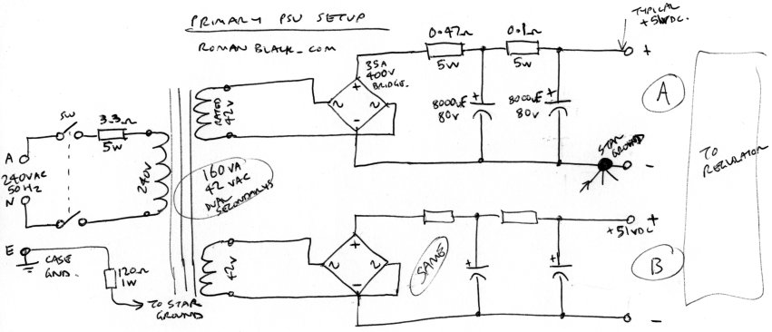
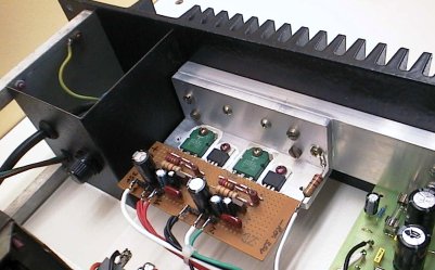
Primary power supply
I modded the psu by removing one of the original 2 transformers. The
remaining transformer seems about 160va which is still twice as large as
it needs to be. A second 35amp bridge rectifier was added, this was
needed to separate the + and - supplies completely as this is required
by the dual regulators in the secondary psu. This was easy enough as the
transformer had 2 independent output windings and I had a matching
rectifier bridge in my junkbox.
I kept all 4 of the big capacitors, 2x 8000uF caps on each +/- side so a
total of 16000uF per side. I added some 5watt resistors (the white ones).
A 0.47 ohm resistor before the first cap and a 0.1 ohm resistor between
the caps. This forms 2 low-pass RC filters and reduces ripple to a few
millivolts at normal listening levels. Sometimes it's known as a Pi filter
when used in a psu.
This system in an amp psu may be a little controversial when other home
builders are using fast recovery rectifiers and very low resistance cabling
(what on earth are they thinking???) but it provides a much better filtered
dc to go to the regulators. I have also seen this in many quality audio
amps when I was working as a repairer.
The rather large resistor (0.47 ohm) between the bridge rectifier and
the first cap increases diode conduction angle which drastically reduces
current pulses during the cap charge cycle hence reducing; radiated emf,
diode switching transients, ground loop current and of course dc ripple.
It also helps a bit with inrush current when the amp is first turned on.
With the extra filtering from the duel low pass filters it was not
necessary to use small caps across each of the 8 diodes, and also the
secondary regulator will easily remove any small hash from the primary
psu. The result looks very nice on the oscilloscope, with no load (or low
listening levels) its at 51vdc with a few millivolts ripple. At higher
listening power (near the pain threshold) its 50vdc and the ripple
is WELL under 1 volt and with a nice looking duty cycle. The voltage
droop of only 2% and such low ripple gives you an idea of how overpowered
this primary psu is.
Regulated (secondary) power supply
Why bother with regulated power?
There are very few amps that use a filtered regulated dc voltage to power
the amplifier. Normally the psu provides a semi filtered dc where 100Hz
(or 120Hz) ripple might be as bad as 15%. The amplifier circuitry is
designed with high levels of negative feedback for supply ripple rejection
and theoretically they can accept this poor dirty power without affecting
sound quality.
Think of the amplifier circuit as a car with great suspension. You can
drive it on a really bumpy road (ripple) and the car still rides smooth,
kindof. Then add in constant changing ride height variances (the sound
signal) and dynamic problems like tyres bouncing (speaker L/C dynamics) and
with all 3 factors going wrong at the same time you risk feeling some
bumps. Amplifiers have a finite limited ability to pull that output high
or low to the exact voltage position required at that point in time,
and feeding the amp with dirty power bumping up and down can and does
cause distortion.
Likewise with loud transients (the pumping guitars and
drums of rock music) each amp channel will cause pulses of current
drain that sag the psu voltage which is passed on as even worse rippling
power to the other amp channel.
The experts can argue forever about whether regulated filtered power
is actually necessary for the best audio but after hearing this amp
finished I'm convinced. My amp produced the characteristics reported by
so many others with regulated psu amps; superb clarity where every little
subtlety is revealed, fantastic right/left channel separation, total
absence of any hum or hiss and complete lack of murkiness; ie even when bass
frequencies are pumping loudly the tiny treble subtleties of other
instruments remain crystal clear.
So you can rave on about how your car has the best suspension in the
world and rides great on your bumpy road - but I'll still be driving on
my flawlessly smooth road...
Regulator design.
I looked at a few options, either using 4x LM317 regulator ICs for
independent amp regulation or 2x LM350 regulators for about 3A shared
(4.5A peak) by both amplifiers. Both of these designs would be simpler
than the design I chose but had current limits which could possibly
cause regulator dropout when faced with high current transients.
Since this is a studio amp for heavy rock with a lot of transients
I went super heavy duty with the regulator. I used a typical high current
regulator design with feedback. A LM317 regulator IC is used as the voltage
controller which operates a massive PNP power transistor. The PNP devices
I used are 2SA1265, 140v 10A 100W in a nice green flatpack. Ironically
these were originally output devices in an expensive high power audio amp
that was scrapped due to flood damage years ago. Capable of 10A continuous
or easily 20A transients these are tough little beasts.
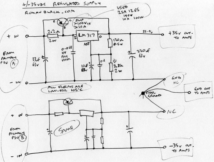
The LM317 acts as the regulator for low current use, up to about 300mA
at which point it has developed -0.7v on the base of the transistor
so then the transistor passes the bulk of any currents above 300mA.
The LM317
goes into current limiting when it hits about 1.7A, at which point the
transistor base is about 1.4A at a forced beta of better than 8,
so it looks like the regulator should easily supply 10A without dropping
out of regulation.
Since the chip amplifier has internal limiting at transients of 100W
(under 4A), the regulator will supply both amp chips running into
limiting long before the regulator ever runs out of steam. A solid
regulated filtered +/- 35vdc the whole way. Very nice.
I used small 47uF caps at the regulator input and 220uF low esr caps
at the regulator output. Some small caps decouple the LM317 itself
and also a 10uF low esr cap further decouples its adjust pin. It is
constructed on veroboard (0.1" stripboard) and its not a great design
in terms of layout but most of the current passes direct through E-C
of the transistor and the other current paths are low current with
plenty of bypass capacitance. I've worked with LM317 chips a lot over
the years and never had trouble with oscillation when they have caps
on all 3 pins. Likewise this regulator seems to work very nicely.
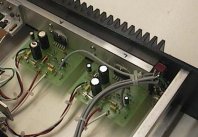
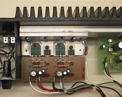
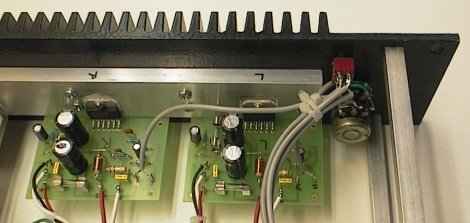
Regulator construction.
What you see here is the second regulator attempt. The first was the
same circuit, but had the 2 (green) PNP transistors mounted vertically
to the main heatsink and the 2 (black) LM317 with individual small tag
heatsinks just free standing on the circuit board.
However after testing with music it was obvious the amp will be used
mainly at lowish sound levels, at total currents under 500mA. In that
case the LM317 disspate the majority of regulator heat and it was silly
for that heat to be left inside the amp case with the front heatsink
doing nothing. With the regulator redesign the LM317 chips were also
mounted to the main front sink so all that nice heat can be brought
out to the sexy front panel heatsink (where I can soothe my stiff
guitar fingers on it, hehe).
Directly behind the heatsink is a 300mm length of 40 x 10mm alloy bar
that the regulator assembly and the 2 amps sink to.
The new regulator bracket is 100mm long, a piece of 40 x 40 angle 6mm
thick. I cut it to 40 x 30 x 6 to bring the power devices closer to the
front sink. Thermal coupling is good, less than 1'C difference between
the bracket and the main 40mm internal heatsink bar. The front panel
sink runs another 1 to 2'C cooler still. Even with the amp pumping loud
the front sink remains only "nice and warm" so its actually very pleasant
for tactile appreciation and so much more fun than being hidden at the
back of the amp!
Dual LM3876 "Gainclone" amp modules
Dont forget to take out the trash!
The original ETI5000 mosfet amp modules (sorry no picture) went straight
in the bin complete with crispy fried pcbs, carbon garnish and charcoal sauce.
And I'm sure I saw a bright orange hair from some technically
overconfident primate.
Love and hate.
Well while waiting for the new amp module kits to arrive I did a lot of
reading on the internet about these chip amps. I love what they can do
with a single chip amp; very low distortion, low parts count, lots of
protection features, rave reviews etc.
And then I hate the crappy kit modules that arrived. Grr. After days
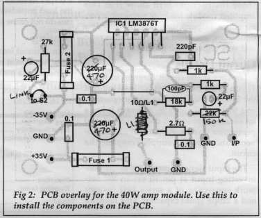
of seeing good layout pcbs for gainclone style kits and reading and
rereading the LM3876 datasheet about good pcb design with attention to
current paths and feedback paths the Silicon Chip (aussie magazine)
kit pcb looked like crap. I know there are some smart guys at Silicon
Chip so I can only surmise that this pcb was designed by the office
girl having her first play with the pcb autorouter software while
all the "men" were out at lunch having a beer. Did I say grrr...
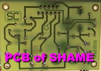
The layout suffered particularly on the 2 supply caps NOT being close
to the chip with very large tracks as specified in the datasheet.
They are away from the chip with rather spindly tracks connecting.
The ground track is a complete disgrace and meanders about more
than the upper Amazon.
The feedback loop is 60+mm long and worse still the feedback resistor
could have been placed right near the chip where there is a surplus
of space! I know someone at SC did read the datasheet
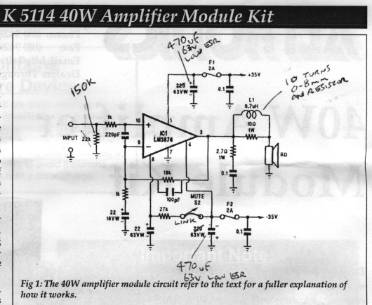
because they used the input RF filter, output zobel snubber and
output L/R almost verbatim. They also added what looks like a
"kludge", a 100pF cap across the feedback resistor obviously to
reduce amp gain at very high frequencies and kill any HF oscillation.
I dont know if they actually did have trouble with HF oscillation
but I doubt they did with the zobel and L/R on the output.
I guess they added this as an extra safety precaution
and since 100pF won't attenuate amp gain at audio frequencies
it seems a good call.
Now some more hate moments with the kit supplier who I will not name
(it was Altronics that's ALTRONICS)... Hmm first there was no pcb
top artwork to show where the parts go, sounds minor but it also
shows the names of the connection pins (not so minor) and adds a
lot to a professional look. How much does a top silk screen cost??
I can see that SC produced the overlay artwork, just Altronics skimped
on the 5 cents per pcb to have it printed. I used a felt tip sharpie
pen to write the pin names on the pcb. Grrr.
And it gets worse. The pcb was designed for large supply caps
with 7.5mm lead spacing. The caps supplied were 220uF which is both
pathetic in size and with 5mm lead spacing wont fit the board.
Even worse almost all the holes on the pcb are 0.8mm drilled.
Half the parts would not go into the holes starting with the
chip!! I tried some hole "tweaking" until I realised the
enormous magnitude of their incompetence
and had to go find a 1mm pcb
drillbit and handdrill and start redrilling holes during the middle
of construction. Even to insert decent supply caps (I used 470uF
63v 105'C low esr) required drilling out to 1mm holes. Another
design fault where the chip mounting surface does not reach the
edge of the pcb didnt bother me due to my heatsink setup BUT
if I had tried to use their supplied heatsink would have meant
that all the chip leads had to bend to a stressful unprofessional
angle to fit. What if someone tried to build this kit and didnt
have a 1mm drill and confidence to fix all the errors??
Did I say grrrr?
Ok enough complaining.
I tossed all the garbage electros supplied
with the kit and used low esr caps of 105'C. From experience the
105'C caps have much better reliability than standard 85'C caps
and maintain their correct value though a larger heat range.
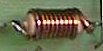
I tossed their pissy 0.4mm wire and wound the 10 turn output
inductors with 0.8mm enamelled wire, nice. I replaced the 22k
input resistor with 150k as the inputs are always connected to
a 10k pot anyway and I wanted good gain from my CD player. All the
resistors were checked with a multimeter and the rest of
construction went ok.
Hmmm... Do you think I need a bigger power supply??
The modules were powered up with a lab power supply for safety and
tested under 30mA quiescent (perfect) 2mV dc offset (perfect) and then
nice in/out waveforms on the oscilloscope with about 20:1 gain (perfect).
I still need to tidy up some wires etc and use some silicone to secure
things against vibration. I was going to bend up a metal shield to completely
separate the psu sections from the amp modules, but as it makes NO hum
even at full volume (sounds like a black hole!) it just doesn't
seem necessary.
Heat testing
I connected a sinewave generator and an 8.0 ohm 60W resistive dummy load.
The sine input voltage was set at 2.8v peak to peak at the amp input
(before volume pot). Input and output waveforms were
both monitored on my dual trace oscilloscope. All temperatures were measured
with infrared non-contact thermometer, voltage readings with my good Fluke
multimeter.
First heat test was one channel run at 1kHz sinewave continuous.
After 20 minutes for temperatures to stabilise;
Test 1 Output power = 36v p/p = 20W RMS
Ambient temp = 29'C.
Amp gain = 18.46
LM3876 package temp = 75'C
LM3876 package dissipation = 70.5v 775mA = 54.6W (-20) = 34.6W
Rear heatsink bar temp = 59'C
Regulator transistor/chip temp = 54'C
Regulator dissipation = 11v 800mA x2 = 17.6W
Regulator output ripple voltage = 0v
Mains Transformer temp = 39'C
Bridge Rectifiers temp = 41'C
Primary PSU supplying = 46.1v 800mA x2 = 73.7W
Primary voltage sag = 51 - 46 = 5v
Primary ripple voltage = 0.24 vac
Front panel heatsink average temp = 51'C
Test 2 Output power = 51v p/p = 40W RMS
Ambient temp = 29'C.
Amp gain = 18.46
LM3876 package temp = 76'C
LM3876 package dissipation = 70.4v 1055mA = 74.3W (-40) = 34.3W
Rear heatsink bar temp = 60'C
Regulator transistor/chip temp = 58'C
Regulator dissipation = 10v 1080mA x2 = 21.6W
Regulator output ripple voltage = 0v
Mains Transformer temp = 40'C
Bridge Rectifiers temp = 43'C
Primary PSU supplying = 44.7v 1080mA x2 = 96.6W
Primary voltage sag = 51 - 45 = 6v
Primary ripple voltage = 0.28 vac
Front panel heatsink average temp = 52'C
Comparison LOUD music listening level!
Ambient temp = 28'C.
Primary PSU supplying = 51v 200mA x2 = 20.4W
LM3876 package temp = 42'C
(each) LM3876 package dissipation = 70.6v 90mA = 6.3W (-?)
(each) Music average power (estimated) = 2W RMS
Front panel heatsink average temp = 38'C
I learned a few interesting thigs doing these tests. First, that there
is no way in hell this amp is going to be run at 40W RMS... Ever.
Or even 20W continuous.
My near field monitors (speakers) are quite efficient with just a few
watts, getting painful at probably 3w and even cranked up to stupid
level with ringing eardrums that can't hear any detail is maybe
10w based on my volume pot position.
Also interesting was the performance of the regulator, even at
1kHz 40W continuous there was NO sign of any 100Hz or 1kHz ripple
on the regulator output viewed with the oscilloscope. Cranking the
sensitivity of the scope right up to show microvolts just brought
up noise from the scope leads, the same noise even with the lead
disconnected and shorted etc. So that baby IS rock solid.
Re the mains transformer it was cranking out 96+W with just one amp
running at 40W RMS. So that would be 200+W with both amps running
at 40W. Surprisingly the low sag of 6v at 96W and low transformer
temp 40'C after 20 mins leads me to believe that this transformer
might indeed be good for 200W. I dont need this to be a P.A. amp
so I'll never find out. I would have tested dual 40W operation
but I would have had to make a second dummy load and frankly
just didn't want to abuse the amp with power levels it will never
see.
Frequency response
Similar setup; variable freq sinewave generator, both channels tested
individually, output 20v p/p (6.3W RMS) into 8.0 ohm resistive load.
Both input and output sinewaves were monitored to make sure. I didnt even
bother to check frequencies above 20kHz as it's probably good up to
110kHz as Silicon Chip stated in their original specs. Convert it
to dB if you like but it really doesn't get much better than this;
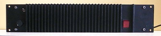
Other mods and additions
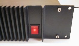
The main ac power rocker switch was tired and its neon light dull. So
now it's new, reliable and most shiny. A 3.3ohm 5w resistor was placed
between the power switch and the 240vac transformer winding which might
provide some softening of turn-on inrush current and some mains spikes.
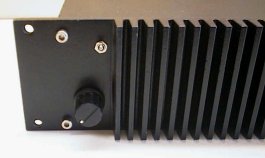
An old but unused and good quality dual gang 10k linear pot was added
to the front panel, and capped with a nice businesslike black knob.
I also added a toggle switch and a second set of RCA inputs so I
can easily switch between my studio mixer console and my good Pioneer
CD player. Both pairs of RCA inputs were moved to the far side of the rear
panel well away from the psu.
The 4 main screws holding the front panel to the chassis struts were tiny,
ugly and rusty. I drilled and tapped 5mm metric threads into the 4 struts
and used nice large stainless steel socket head bolts. Much stronger and
suits the tough looking front panel. Internally there were 10 holes on
the back of the front sink that had self tap screws in and of course were
munched/stripped. I drilled and tapped these to 4mm metric threads 6mm deep
(such fun tapping short blind holes) to give real good thermal mounting
of the internal sink bar to the front panel.
So how is it??
Well in a word... Superb. To add some more words I would say clarity,
separation, pump, zing, pow!, sparkle. These LM3876 "gainclone" chip amps
have a rep of sounding great so I wasnt surprised.
And the rock-solid regulated high-current psu only adds magic to that
sparkle. I'm not a stranger to good audio amps, over 20 years repairing amps
I've had the chance to listen to hundreds of amps. I've also had a little
experience in 2 commercial recording studios with great amps and
acoustics and years of experience with my own little studio setup
in the late 80's so you can say my ears are trained to pick up some
of the subtleties in music, although I don't claim to be
"golden eared" - maybe "sterling silver eared?"
Also I don't have world-class speakers at the moment but even with my
imperfect speakers this amp sounds right up there with the best of
them.
Power wise it's about perfect for my needs, at regulated +/-35vdc the
datasheet says 60v p/p waveform before clipping so that's a huge
amount of headroom for studio use where it will run at about 2w to 5w
or so... Even when used as my guitar amp with my Boss rack stereo
FX unit running DI. The amp is much louder than you
might expect from the average wattage figures,
something common in amps with very beefy psu's due to
their ability to deliver all the transients with zero attenuation.
I was shopping for speakers the other day in a department store and
saw a little plastic ghetto blaster thing with big stickers on it
proclaiming "230W RMS"... It actually said RMS. I laughed.
And the visual "presence" of the amp is nice. It's chunky, blokey,
scratched cosmetically and obviously "been around" but also sleek
and black and industrially businesslike.
As a studio amp it hollers out "respectable"
with just a whisper of "brutal". I've always desired one of these
heatsink-fronted power amps and this rebuild delivers just what I
wanted.
But heck I would be delighted if everything in my house had
a big black heatsink on it! (grin)
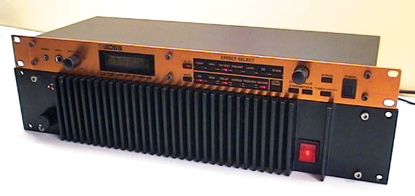
Beauty and the Beast!
Resources
If you want to build "gainclone" amps there are a lot
of better kits available than the ones I got!
Better choice 1: Elliot Sound Products
have a pcb with 2 amps on the 1 compact pcb.
Better choice 2: Chipamp.com
sell nice kits and pcbs for amps and main psu.
Better choice 3: Audiosector.com
sell nice kits and pcbs for amps and main psu, even with optional
gold plated pcbs.
SigJenny free
PC software
audio sinewave and sweep signal generator 10Hz to 20kHz (2.5Mb)
WavMak is free PC software I made that enables you to create
very specific waveform shapes for audio testing.
LM3876 Amplifier chip Datasheet (362Kb)
LM317 3pin regulator Datasheet (144Kb)
- end -
[Back to Home Page]