[Back to Home Page]
www.RomanBlack.com
High res cap meter with PIC 16F628
High resolution capacitance meter measures in 0.01pF digits. Total range 0pF to 50uF.
- 27th Jun 2011, Updated 25th may 2013.
Another PIC based capacitance meter?
Although there are a few PIC based "pico" capacitance meters on the internet this
design has some advantages over the other designs I have seen;
1. It has very high resolution; from 6 to 7 digits! (Others have 3 or 4 digits)
2. It has a wide range; 0pF to 50uF. (Others do not go over 0.1uF or 1uF)
3. It uses only a single cheap PIC 16F628. (Others use two ICs)
4. It does not need calibration! (Others need calibrating with a special test cap)
5. It can do auto-zeroing, floating zero and negative capacitance (relative to zero).
How it works
For absolute simplicity I used a PIC16F628. The oscillator uses the PICs
internal comparator so no second IC is needed.
The oscillator is an RC comparator oscillator that switches between
1/3 Vdd and 2/3 Vdd, this is a proven system and the frequency is reasonably
unaffected by small changes in the 5v Vdd.
The three 1k5 resistors (green) set the threshold voltages at 1/3Vdd and 2/3Vdd
when the comparator output switches. (The PIC is a better comparator than many
dedicated comaprator ICs as its output has good push-pull low-Rds FETs).
The oscillation period (freq) is set entirely by RT and CT. RT is a 1% metal
film resistor which I measured on my multimeter at 10.00 kohm. Now the only
thing that sets the oscillation period is the test cap CT.
The final stage is the PIC timer, that measures the oscillation period
very precisely compared to the PICs xtal. And a math calc is done to scale
the period to capacitance in farads.
Precision period measuring!
The PIC measures the RC oscillation period by using the PIC's internal hardware
capture (CCP1). The PIC xtal is 16MHz so the PIC timer runs at 4MHz.
It adds consecutive captured periods until there is a total accumulated
time greater than 2 million counts (>0.5 second). The only error can be
the edge error for the first and last capture, so the error is limited
to 1 part in 2 million at each end, a total possible error of 1 PPM
(1 Part Per Million).
Now it has a precise captured total of periods the average period is
determined by dividing the total period with the number of periods
captured. As the total is always just over 2 million it is scaled up
to 2 billion before the division, to give a lot of accurate decimal
digits after the division.
For example;
"10nF" cap, oscillates about 435Hz
218 consecutive periods are captured, a total of 2004597 counts
Math; (2004597*1000)/218 = 2004597000/218 = 9195399
(so the average period is 9195.399 counts)
A second process is used to convert that result to picofarads;
(9195399*100)/scale = 919539900/919 = 1000587
1000587 is then displayed as; 10005.87 pF
Another small cap example;
"100pF" osc about 43500 Hz
21751 periods are captured, a total of 2000091 counts
Math; 2000091000/21751 = 91953
Scaling; 91953000/919 = 100057
100057 is truncated and displayed as 100.05 pF
All the math and scaling systems have been chosen to give the best precision
possible from the 32bit unsigned long variables used in the firmware,
without resorting to float or 64bit variables that would have needed a larger
and more expensive PIC.
There are three display ranges;
0pF to about 18000 pF, format; "PPPPP.DD pF"
18nF to 999nF, format; "NNN.DDD nF"
1uF to 50uF, format; "UU.DDDD uF"
Display accuracy?
In the pF display mode the display accuracy is about two final digits; +/- 0.02pF.
In the nF and uF mode the display accuracy is better, at +/- 1 final digit.
"Real" accuracy!
The "real" accuracy depends on the internal calibration, with my
PIC, 10.00 kohm resistor and 16MHz xtal the calbration is accurate to
better than about 0.2% of the capacitor value, based on some test caps.
You should be able to improve this further by using a trimpot in series
with the 10k resistor (ie; 9.75k resistor + 0.5k trimpot) and trimming
for much better than 0.2% accuracy by using some precision test caps.
However the cap meter was designed for better than 1% accuracy as a
convenient hobbyist build without needing any special equipment or special caps.
The benefit of having the high display resolution (lots of digits)
is that it allows caps to be compared
to each other, and allows fine resolution capacitance changes to be seen,
especially things like thermal changes and variable capacitors.
Even with a fixed cap you can see the cap value change
as you waft cool air at it with a book and cool it a fraction of a degree.
Or you can see the capacitance rise by 0.01pF when you place your finger
1 inch away from the cap!
Advanced features
The cap meter has an advanced floating zero feature. Pressing the button
zeroes out any cap value that is displayed. The meter can be zeroed any time
it is in pF mode (up to about 18000pF).
The meter can display negative capacitance values compared to the
zero point. So if you zero it on a good 1nF cap, other 1nF caps tested
will read as + and - the difference, so it can be used to check cap
error against a known good cap.
The second advanced feature is the auto calibrate mode.
If the button is held for 2 seconds the cap meter enables auto zero calibration.
Then any time when there is no test cap connected (<3pF on test leads)
the cap meter will slowly "trim" its zero calibration by about 0.01pF
every second so that it is always correctly at zero! When in autocal mode
it can still be zeroed by pressing the button.
Building it
The schematic looks messy but it is easy to build! For energy efficiency I used
a low-quiescent current +5v regulator instead of a standard 7805, to cut
current consumption down from 13mA to 6mA. But a 7805 works fine if that is
what you have.
If you don't have a 1% metal film 10k resistor (or want to adjust it
for high precision) then replace the 10.00k resistor with a resistor and trimpot
and then adjust the trimpot to equal 10.00k or to match a precision test capacitor.
NOTE! You should also use 1% resistors for the 1k5 resistors for best results!
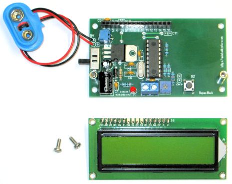
As the circuit is VERY simple (it's just a PIC and a few parts) I made
it on veroboard (stripboard). It is really not worth etching a PCB
for this project! A small SMD 5v regulator is soldered to the bottom
of the PCB, all the other parts can be seen below;
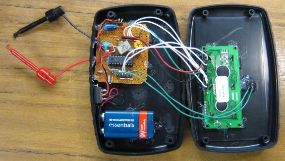
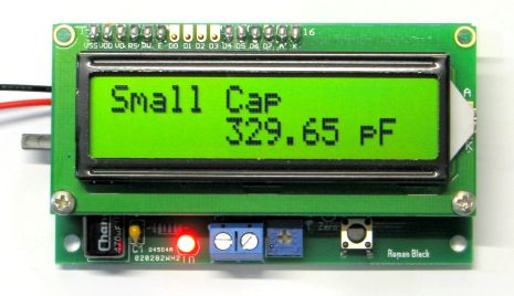
The board was hot melt glued into a $6 plastic case, and the 16x2 LCD and button
were glued into the case top. A slide switch and 9v battery were added for the
power. It's important to glue the parts down so things don't move around much
as this can affect the capacitance reading.
The 16x2 text LCD is an older style with NO backlight and very high reflective
screen, it has great readability and only uses about 2mA. The whole cap meter
only uses about 6mA so battery life should be very good.
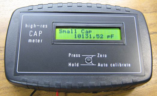
Measuring a 10nF capacitor!
A black and white front panel was drawn in CorelDraw and engraved.
You can get small engraving jobs like this done at any "Trophy Engraving"
shop for a few dollars especially if you can provide the engraver with the
format he prefers so it is less work for him!
PIC source code is not included. It was hard to fit all the 32bit math
into the small PIC 16F628 which only has 2k ROM, so it became a little messy!
My C code has some
stripped-down routines and some gotos etc and I won't release it in a messy form.
But the process is described above if you want to create your own source code,
or you can just use the HEX file below to program your own PIC 16F628 or 16F628A which
are very common PICs.
NOTE! Hex file below is now improved v1.1
Update 25th May 2013. My original HEX file had a minor display issue
where leading zeros were not shown correctly, ie; "0.01pF" was shown as
" . 1pF". I had originally let that go as the PIC ROM was 99.9% full and
it was a very minor issue.
However this project has been fairly popular, so on a user's request
I have now fixed the leading zero issue. This was a minor display tweak,
all other code remains the same so I have removed v1.0, and the HEX file
below is now v1.1 and includes the fix.
Download CapMeter.HEX file
Testing
Testing is quite straightforward. When it powers up the display will read the
total value of the internal 270pF cap plus some extra capacitance from
PCB tracks etc. Mine reads about 320pF. The oscillator will be running about
220 kHz.
Then press the zero button. The display will say "Zero Cal" and
will then read close to zero, although it may be a fraction of a pF out.
Mine reads about -0.05pF after zeroing and it may change a few counts
as the internal cap warms up. With such a sensitive meter it's normal to see
caps drift by a small amount with temperature changes!
You can re-zero at any time, which may be necessary after moving the leads
as this can make a difference of 0.10 to 0.20pF or so. Of course this will
not matter if you are measuring any cap larger than a few pF!
At this point connect a cap to the leads and its value will be displayed.
If the oscillator stops or the leads are shorted, or a cap larger than
50uF is connected the system times out and the display will show "Error"
and alternate between "Error" and "Large cap" as it tries to find a cap.
Auto zero calibrate is selected by holding the button down for 3 seconds.
Auto mode can be toggled on and off. In auto mode it will SLOWLY trim the zero
point by 0.01pF per second or so, but only when there is no cap connected.
Auto mode is probably best for most cap measuring unless you need to measure
very small caps.
New! 16th July 2011. I've been asked to take part in a pilot program on the
Electro-tech forum where some of my projects are linked to a thread
where you can;

NEW! Kits for sale
12th March 2012 - I was emailed out of the blue by Alexey from
Radiohobbystore.com, who said he had seen my CapMeter project and wanted
to make kits.
I agreed as I had no intention of making or selling kits, so Alexey has
designed a neat easy-to-assemble PCB based on my schematic and is selling
kits for a very reasonable price, see
Kits for sale here!
Update 1st Dec 2012; Alexey now has an improved PCB kit for sale.
I have no formal business arrangement with Alexey and I don't receive
any payment from kit sales. So please email him for tech support with the
kits. :)
Thank you Alexey for producing the kits, and for my readers here please
consider buying one they are very reasonably priced and will make
construction simple and reliable.
- end -
[Back to Home Page]