This can be "cheated" to just use one pin and timed-length pulse. An RC network is used to provide a time delay for the DAT line to change. Very short pulses mean that a 1 bit is shifted in. With a long enough pulse the DAT voltage drops low enough so that a 0 bit is shifted in when the CLK line goes / again.
The system above works pretty good, all that is required is a Resistor and Capacitor, and then the pulse length detemines if each new bit is shifted in as a 1 or 0.
The only drawback is that the data on the 8 parallel outputs changes as the new bits are shifted in. For many applications this doesn't matter, as it happens very quickly, generally less than a millisecond to shift all 8 bits in. So it can be used for things like LEDs, LED matrixing and keyboard matrixing etc.
Shift1 LATCHED system for driving LCDs
One of the things I wanted to use the Shift1 System for was driving a text LCD from 1 PIC pin. This is a very useful thing for me as I have lots of cheap shift register ICs and can then add a LCD to any PIC project that has ONE spare pin.
To drive a text LCD needs 6 pins; 4 data, RS and E. The E pin must be treated carefully so the basic Shift1 system shown above won't work. It needs a LATCHED system where the shift register's parallel outputs don't change until the register is "latched".
The Shift1 latched system is just an extension of the same concept. So 7 bits are sent first, then the 8th pulse is very long which triggers the latch event. I specifically designed this for the 74HC595 shift register IC which is common, cheap and has 20mA output drivers.
One obvious problem is that the last bit shifted in (bit0) will always be a zero. I though this was an acceptable tradeoff for such a neat system as to drive a text LCD only needs 6 bits, and it gives 7 bits.
A less obvious problem is that it is a little slow. Driving an LCD needs the latch data to be sent 4 times for each text character sent. Twice for the 4bit data, and twice to make the additional E pulses. This can take up to 4mS to send a character (usually around 3mS). It is fast enough for most display purposes and menus etc, unless you need to display a LOT of fast-changing numerical data.
Testing my Shift1 Latched protocol
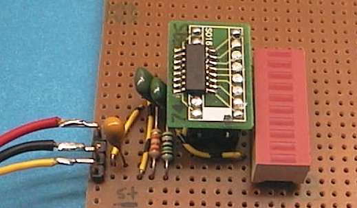
The "proof of concept" worked perfectly first go. I only had the 74HC595 in surface mount size, so I used a SO16 adapter board into a DIP16 socket.
The RC filter values are the same as shown in the schematic below;
1k5 2.2nF
33k 2.2nF

These values were chosen to give good comms speed, ie the shortest low pulse is 1uS which is a good value for PICs. The 1:20 ratio of the resistors was chosen to give a good safety margin between the low period needed to shift a low bit, and the low period needed to cause a latch command. I tested the shift register 8 output pins with a 8 bar LED. All 7 shift register pins worked perfectly, as expected.
I tested all the period times on the oscilloscope, and ended up with the uS periods shown in the diagram above. They have a safety margin built in, you may be able to use shorter periods.

The next test was to hook up a text LCD... I connected 6 of the 74HC595 pins to a typical LCD and added a 10k contrast pot. Then I adapted my C LCD code to write to the 6 pins through my Shift1 timed protocol. Everything worked fine, and was tested on a few different LCD displays. It's a success, one PIC pin driving a whole LCD and all that's needed is a shift register and a few discretes.
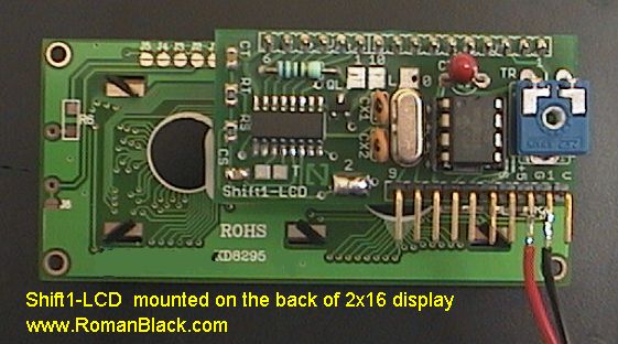
A practical Shift1 LCD driver
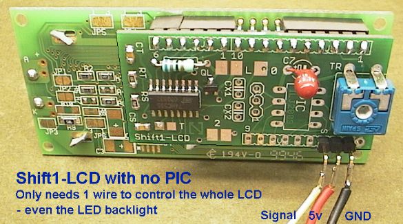
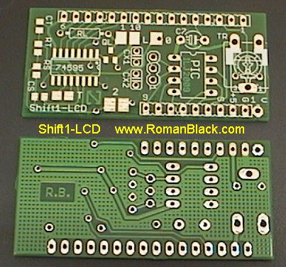
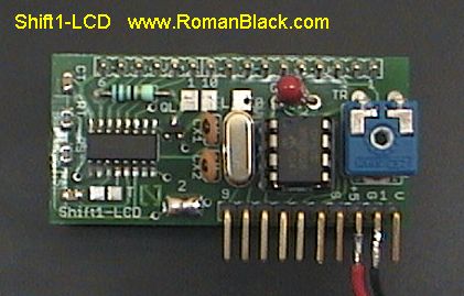
I designed a small PCB for using the Shift1 system to drive a text LCD. This only needs a 74HC595 shift register IC, 2 resistors and 2 caps, and a contrast trimpot to drive an LCD from 1 PIC pin.
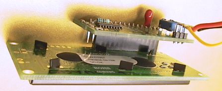
The PCB mounts directly behind the LCD display, on the 16pin LCD header.
I also added space on the Shift1-LCD to include an optional 8pin PIC. As it only needs 1 pin to drive the LCD that still allows many simple applications with a little PIC. Another addition was a P-FET to control the LCD backlight (if it has one). This is done using the spare bit, so now all 7 outputs of the shift register are used and the PIC can turn the backlight on/off without needing any more pins.
The Shift1-LCD module is available as a low cost kit in 2 forms;