[Back to Shift1-LCD Projects Page]
www.RomanBlack.com
Drying oven controller
A quick easy build temperature controller using the Shift1-LCD kit
- 14th Nov 2009.
Warning!
This project uses mains voltages! It uses a mains-rated
relay to switch 240VAC to a small heater element. Do not attempt to construct
mains powered equipment unless you are confident in your ability to construct
something safe and which complies with relevant electricity laws. This is
NOT an example of how to build commercial mains operated equipment. It is
an example of an easy fast low-voltage project that relies on a mains-rated
relay to do the actual 240v heater control. PLEASE do not attempt anything
unsafe!
This temperature controller operates a small low-temperature paint drying oven
used for modelmaking. The oven is a wooden cabinet about the size of a small
wardrobe. The oven temperature can go as high as 70'C but generally it is
operated at 35'C to 50'C. Display and control resolution is 0.5'C.
The temperature controller keeps the oven at an stable temperature within
about 1'C of the temperature setting.
This uses a LM335 temperature sensor inserted in the drying oven, and it
switches a relay on-off to control the heating element in the oven. The heating
element is a set of 240v light bulbs in standard bayonet type lightbulb sockets.
There is also a small 12v fan inside the oven to circulate air and keep the
temperature constant in all parts of the oven.
Generally the oven uses two 100 watt lightbulbs, (a 200W heater) although the
5 amp mains-rated relay in the controller will safely control 500W total. With
a larger relay this device could control any size oven.

This controller offers an additional feature from the original SH1_Temp software.
It has a 999 hour timer. When the red button is pressed the timer is reset
back to 000:00:00 (hours:mins:seconds). This is a useful feature when some paints
need 75 or 100 hours of drying at a specific temperature, the timer is reset to zero
when the models are put in the oven and the timer counts up from there.
The timer itself is just a display, it does not turn anything off.
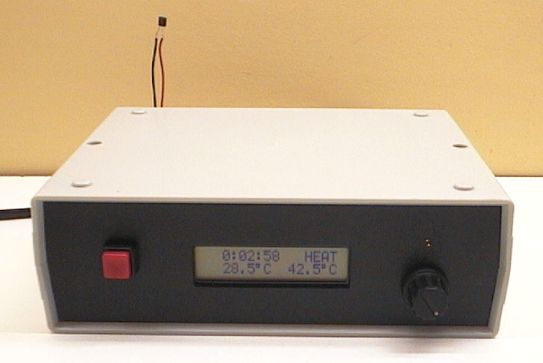
The display shows;
000:00:00 count-up timer
HEAT / COOL indicator (also has a 3mm Yellow LED)
Actual temperature in the oven (LM335 sensor temp)
Setpoint temp (thermostat setting)
How it works
There are only a few simple components;
BRAIN; Shift1-LCD + 16x2 LCD with orange backlight
PSU; 12v 1.5A transformer, rectifier, 7805 +5v regulator
INPUT; rotary encoder knob, button, LM335 temp sensor
OUTPUT; mains rated relay 12v coil 5A 240vAC contacts, transistor to drive it

The LCD and Shift1 controller are mounted on the front panel. The rotary
encoder knob is in 0.5'C steps (per detent). It can take a few turns to
go from 30'C to 50'C.
It was a very simple project to wire up so a PCB was not needed. The transformer
was bolted down, and a rectifier bridge and 4700uF cap simply glued in place
with silicone. This gives about 11.8v DC. The large value of 4700uF was chosen
to make the unit immune from small mains brownouts up to 3 seconds (so the timer
won't be reset if a mains brownout occurs). There is a 1 ohm resistor between
the bridge and the big 4700uF cap to reduce turn-on current surge and increase
transformer and bridge life.
All mains wiring is fused with a 3.15A slow blow fuse and is kept well away from
the low voltage wiring. It stil needs to have a plastic cover over the relay and
other mains wiring and the wires still need to be secured with silicone. The photos
were taken before this important safety step (so you can see the wiring).

The Shift1-LCD controller is plugged onto the back of the LCD. Then the front
panel wiring was just done point to point between the Shift1 and the button,
encoder knob, and LED. There are only 4 wires connecting the front panel to the
rest of the unit; +5v, Ground, LM335 input, output to relay.
Obviously the LED needs a resistor (680 ohm), there is a pullup resistor needed
on one of the encoder pins GP3 (I used 10k), and a 47uF cap was added on the
analog input that comes from the LM335 temp sensor, this kills any mains noise
picked up by the LM335 sensor which is inside the oven using 3 foot long wiring.

The back panel, left to right; dual RCA socket used for LM335 sensor and 12v out
(12v for small fan inside oven). Then 7805 +5v regulator, and the 240VAC output
socket (for the 200W heater).
The relay was glued down with silicone and a driver transistor soldered to it.
The transistor is not critical at all since the relay coil is only about 50mA.
I think the transistor used was a BD139 45v 2A NPN type. The 12v relay has its
own 1000uF cap, which is connected to the main 12v cap through a 10 ohm resistor
so no relay spikes get back to the 12v supply. The relay also has a 1N4007 diode
across its coil. The relay and wires will get some more silicone later.
Warning!
The relay that does the actual switching of mains
voltage MUST be a mains-rated type. The coil may be 12v, but the contacts should
clearly be marked as rated for "240vAC 5A" or "120vAC 8A" if your mains is
240VAC or 120VAC respectively. All mains wiring should comply with relevant
standards and regulations.
The 7805 regulator is fed with 11.8v DC and provides around 260mA, the LCD backlight
takes most of that; about 250mA. The 7805 dissipates 1.8 watts so it is mounted to
the metal back panel and a small external heatsink. This is plenty, in use it
barely gets over body temperature. The 5v rail has a 330uF cap.

Source code
I have provided the source code, it is in MikroC like all the Shift1-LCD
projects.
Note 1. The source code below uses 2 buttons to set the temperature,
instead of the rotary encoder that I used. This is because buttons are much
more commonly available.
Requires Shift1-LCD with PIC 12F675 (no xtal) and 16x2 LCD
GP0 - (ADC input), connects to LM335 + pin (also put a 47uF cap here)
GP1 - button - adjust SetPoint UP (lo = pressed)
GP3 - button - adjust SetPoint DOWN (lo = pressed)(needs 10k pullup resistor!)
GP4 - out - control heat
GP5 - button - reset timer to 000:00:00
Note 2. The PIC uses the internal RC osc (not a xtal) so you need to calibrate
the timer. Just run the timer for an hour and see how many seconds fast or
slow it is, then change the calibration value in the source code. Although
the PIC internal RCosc is not a high accuracy oscillator I still found
it pretty easy to adjust the timer to within 1 second per hour accuracy.
This is perfectly adequate for a drying oven timer.
Source code in MikroC, also HEX file etc;
SH1_Temp2.zip
19 kb
- end -
[Back to Shift1-LCD Projects Page]