Testing the motor for its max torque gave the following figures (note some of these are out of spec as the motor max power is about 10.2w).
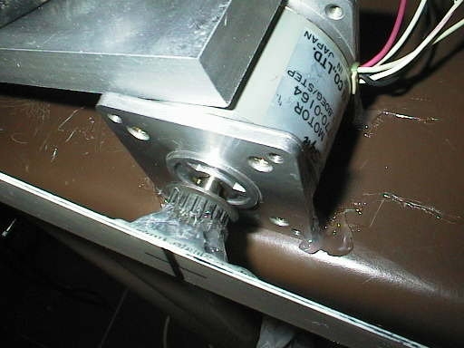
Motor type: "Step-Syn" 23 frame, 72oz/in, each coil rated unipolar 5.1v, 1.0A, (5.1w)

0.71A   7.62v    10.82w   5.95kg/cm (83.9oz/in) two full windings bipolar
0.56A   5.96w    6.73w    5.15kg/cm (72.6oz/in) two full windings bipolar
So running this motor in bipolar drive with the same rated total power gave a holding torque of about 83oz/in. The second row of figures was to match the unipolar torque of about 72oz/in. You can see the bipolar setup was more power efficient, needing less total watts to match the (rated) unipolar holding torque.
Further testing for speed and shaft power showed this old motor did not perform well with a bipolar drive due to it's high inductance, and I changed the drivers to unipolar to get the most from these motors. This is a common scenario when using older motors as these motors were designed and manufactured to give peak performance with unipolar drivers.
Measuring microstep phase angle
This type of testing is normally the realm of laboratories, but again can be done with cheap junk-box equipment. If you are designing a microstepping setup this can be useful to "dial in" the motor and driver to give more accurate microstep sizing.
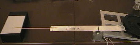
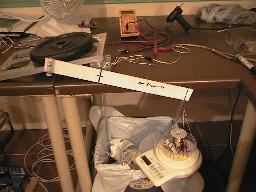
My first go at measuring the phase angle was the above horzontal setup. I glued a thin wooden meat skewer to the end of the ruler and set up a box with a piece of cardboard under the point of the skewer. Total radius was about 45cm, but really was not enough to give the accuracy needed. I also decided it would be handy to be able to measure holding torque at each microstep position, so the setup was modified to be vertical and with a MUCH longer pointer radius.
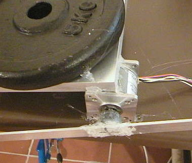
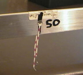
Using a full stick of hot melt glue this time I glued on a 2 metre (6 foot) length of alloy bar 25mm x 3mm (1" x 1/8"). The huge length of alloy bar looked delicate but did not give any problems after I glued the motor down securely. The alloy bar was also balanced carefully before gluing.
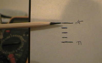
The tip of the pointer was exactly 1 metre from the motor radius. Showing how small microsteps are, the distance from a fullstep to a halfstep was only about 15mm (5/8")! It is easy to understand why stepper laboratories use very expensive precision optical encoders!
During measurement I tapped the motor with a screwdriver between microstep adjustments so it would "settle out" the shaft bearing friction. This seemed to work pretty well.
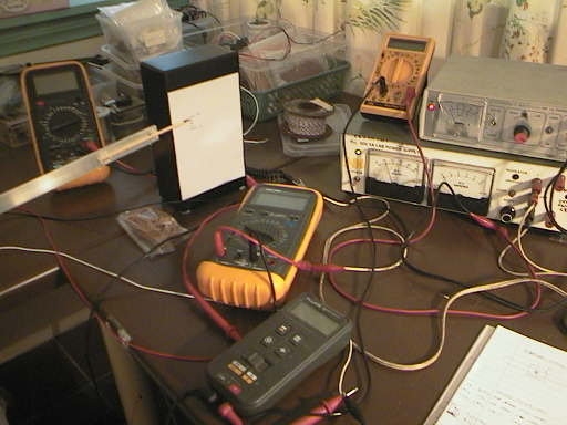
The electrical equipment was very simple and consisted of 2 adjustable bench power supplies and 4 multimeters, to measure the voltage and current through both motor coils.
Again a small cup hung from the lever was used to measure torque, this was placed at 50cm radius, half way along the lever and still above the scales.
The results of the testing are shown below in the standard form of a phase angle quadrant. First the torque of the motor at the halfstep position was measured at rated coil current. This was at coilA = 100% current and coilB = 0% current. This is the black cross at the top of the quadrant.
Then mechanical angle was found by pointer position for each microstep, and the 2 coil currents were adjusted to give the correct mechanical phase angle AND also the same holding torque as the halfstep position.
Note that the actual current values for the mid-step positions were drastically lower than the theoretical current values shown as grey circles. This demonstrates the problem with using theoretical mathematics to try and predict real world situations. In the real world the motor poles are constructed in a way that optimises the magnetic field at the fullstep position, giving a disproportionally high holding torque around this position and maximising torque per motor frame size. This is also the torque value that the manufacturers advertise!
The current values for all step positons are shown as percentages. The top cross is the halfstep with current 100:0. The middle cross (at 45 degrees) is the fullstep with current at 57:57. Between them are the quarter step and 8th step positions.
After testing this motor and a number of others afterward I did discover 2 points common to all the motors that may be of use;