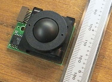
Hacking the TrackBall
When I saw it had an internal microprocessor with the IC number TB2026F I was worried it might be difficult to hack, but it was actually very easy and only took me a few minutes with a +5v supply and an oscilloscope.
It is just 2 quadrature encoders, with CMOS 0v-5v output drivers! This is as perfect as a trackball interface can get;

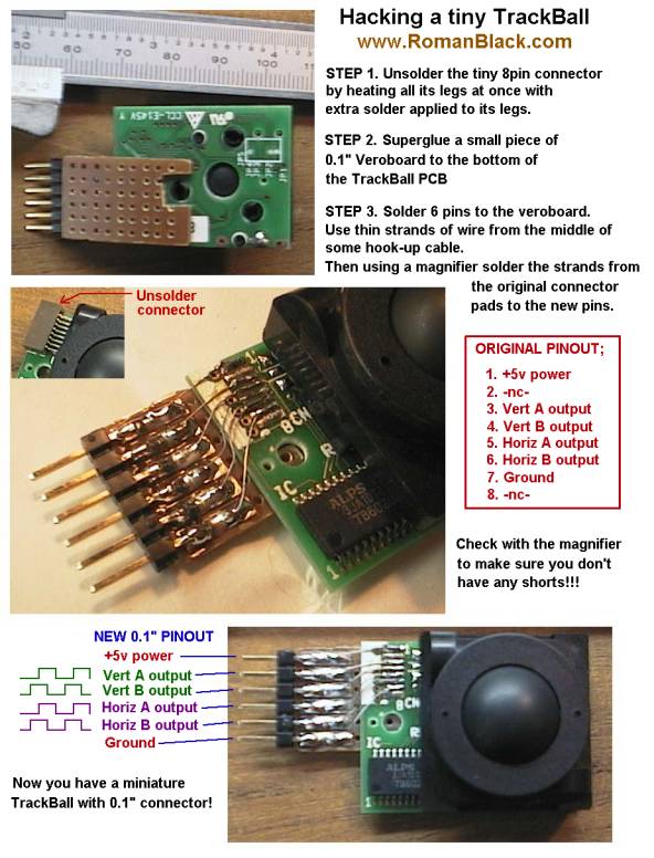
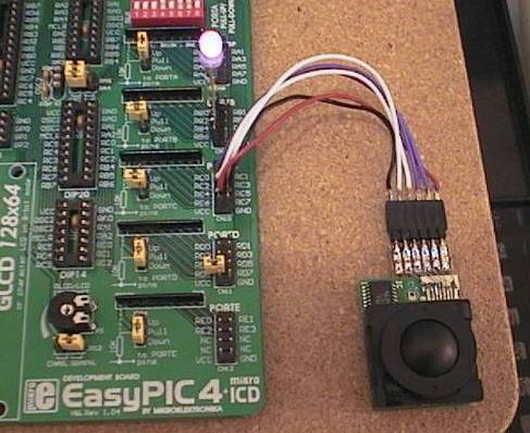
Here's the pinout of the tiny 8pin ribbon connector;
1. +5v power in
2. -nc-
3. vert A out
4. vert B out
5. horiz A out
6. horiz B out
7. Ground
8. -nc-
Probing around the TB6026F micro I could see it going into low power mode after 2 secs after the ball stops moving, and power consumption drops so it must reduce power to the opto encoder devices. However it wakes up instantly and it maintains the output states at all times.
All in all it looks like a very nice little device with inbuilt power management. It could even make a sexy little remote control??
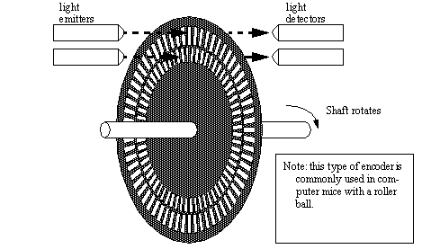
Reading a quadrature encoder output
The trackball has 2 quatrature encoders; one for vertical ball movement, one for horizontal. Each quadrature encoder wheel has 2 light sensors. Here are 2 diagrams I got from the internet, they are not great but will give you the basic idea;
And each quadrature encoder wheel has 2 digital outputs, and makes a waveform like this;
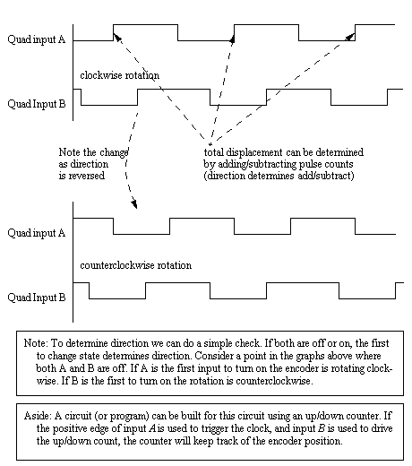
Interfacing to digital logic. As shown in the waveform diagram above, you can just attach the A output to the / edge clock input of a counter IC, and the B output to the up/down control of the counter IC. It will count up or down as the trackball is moved. However this will only make 1 count for every 4 pulse edges, so you only get 1/4 resolution from the encoder, about 64 events per ball rotation.
Interfacing to a PIC or other micro. This is easy and also allows you to get full resolution, about 256 events per ball rotation. To read a quadrature encoder I created my own algorithm which operates quicker and less code than other systems I could find on the internet AND still gives full resolution;
1. Check if the inputs have changed, then;
2. If newA NOT= oldB; direction is +
3. else direction is -
Here is C code I used to read both the TrackBall Horiz(X) and Vert(Y) encoders;
	//----------------------------------------------------
	// read encoder
	encoder = PORTB;
	//----------------------------------------------------
	// check for any change of X encoder pins
	newX = (encoder & 0b11000000);
	if(newX != lastX)   // if changed
	{
		// now check direction (if newA != oldB)
		if(newX.F7 != lastX.F6) x_value++;
		else x_value--;

		lastX = newX;
	}

	//----------------------------------------------------
	// check for any change of Y encoder pins
	newY = (encoder & 0b00110000);
	if(newY != lastY)   // if changed
	{
		// now check direction (if newA != oldB)
		if(newY.F5 != lastY.F4) y_value++;
		else y_value--;

		lastY = newY;
	}
	//----------------------------------------------------
Note! 29 June 2009. I have since found out I was not the first person to invent this simple algorithm for reading an encoder. A similar method was described in a PIC datasheet from the 1990's. This was no big surprise since all I did was analyse the encoder output and refine it down to the simplest possible system that would still return full resolution.
RGB colour/brightness control!
Ok, lets try this TrackBall out on a real project! This is an RGB lighting controller that I am testing to see if it would make a good RGB light switch for mood lights in my entertainment room. This was the original reason I bought the TrackBalls to test. :)
Moving the trackball up/down changes brightness, and right/left changes the colour. I wrapped the RGB colour values in a circle, so just like the light spectrum it goes from red->orange->yellow->green->blue->violet and back to red. It is quite instinctive and a lot of fun. The camera doesn't show the colour right but this LED is a maniac shade of purple.
I wrote the code for PIC 16F877 in C, manually generating the RGB PWM signals in a 64uS interrupt. I soldered plugs on to the LED and trackball so they plug direct into my MikroE EasyPIC4 development board. The RGB led is common anode (+) and the 3 cathodes have 220,470,330 ohm resistors to get it close to white. The 3 cathodes are driven directly from 3 PIC PORTB pins.
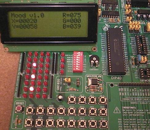
On the 4x 20 char LCD it shows the X and Y trackball values, I wrapped X at 0-383 (3x 128) to do the RGB colour blending and Y from 0-255 to control the brightness.
It's not perfect, I would like finer resolution in the colour adjust and it definitely needs finer resolution in the low brightness settings. But there's no point tweaking that stuff until I get the LEDs in clusters and use some faceted lenses. The individual LED colours don't blend perfectly (when you look close up), they seem to come from different corners of the LED package so some type of facet lens would help there.
Future projects...
I will convert the project above to run on a PIC 16F628A and drive a RGB LED from the TrackBall with minimum parts count.
When it is done I will post the schematic and PIC souce code here! Stay tuned...
- end -
[Back to Home Page]