[Back to Home Page]
www.RomanBlack.com
MikroE SmartGLCD Module
I review the SmartGLCD 240x128 PIC LCD module - 9th Feb 2011
What is it?
The SmartGLCD 240x128 is a self contained module that has a large powerful
PIC microcontroller (which you can program) and a nice large Graphics
display which has an integrated touch panel (so you can touch the
screen and make things happen).
Basically, if you can program PICs you can just program the whole module to
become a self contained device to do almost any task you like, without
needing to build hardware.

Features
The SmartGLCD contains a PIC 18F8527 microcontroller, which has;
48 kbytes ROM
3936 bytes RAM
1024 bytes EEPROM
16 ADC channels
2 MSsP (I2C or SPI ports)
2 EUSART (serial ports)
The SmartGLCD has these hardware features as standard;
Large 240x128 pixel B/W graphics/text LCD (almost 5" x 3" in size)
Colour RGB LED backlight can light up the screen any colour
Full-screen touchpanel lets you draw on screen or press "virtual controls" on screen
MicroSD Card socket lets you plug in memory cards
16 PIC pins on pin headers, both digital and ADC pins
ICSP port so you can program the PIC with your favourite PIC programmer
Internal bootloader so it can be programmed with a serial lead (in the field or if you have no programmer)
Serial pins and other pins brought out to many other pin headers
(Newly discovered) 32k static RAM chip with 24k or more free for you to use
What can it be used for?
The SmartGLCD ia used to develop microcontroller projects and also can become
the finished project or device. So if you need to build a machine controller,
or make a piece of test equipment or a home automation display or a datalogger
etc you just write the PIC software to go inside the SmartGLCD and it is done!
The review
I had been wanting a product like this for years. As a freelance developer
of electronic equipment it has always annoyed me having to make boards and
solder lots of wires to displays and peripherals etc. So I was very happy to
see that MikroE had added a few self-contained PIC products with inbuilt
displays to their product range.

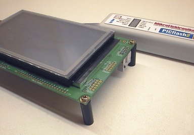
Size is good! The new GLCD modules from MikroElektronika are shown above
for size comparisons. The SmartGLCD 240x128 at a size of 160x90mm (6.3x3.5")
is much larger than the full colour module
and is a 5v module. It also uses a 5v PIC that has 25mA capable port pins.
For my applications these features are important, the physically large
GLCD is great for controllers where the user needs to touch the screen
or that will be mounted on a machine or wall to be viewed from a distance.
Also the 5v operating voltage with 25mA port pins is useful in control
applications as these pins can directly drive solid-state mains relays
and many other industrial devices and sensors.
The smaller MikroE GLCD products are technically more "refined" with
full colour GLCD ideal for photos and can be chosen with a range of PIC18/24/33
chips, but have quite a small display and are 3.3v low-power operated so they
may be more suited for handheld applications than industrial controllers.
Receiving the product
As usual with MikroE orders, the SmartGLCD arrived in a
good solid box and the express shipping only took about 6 days to me which
is impressive coming from the opposite side of the globe.

Note! The PICflash2 programmer, USB cable and tiny USB_Uart product are not
normally included with the SmartGLCD!
As the SmartGLCD is a new product there was no printed manual supplied with it,
but I had already downoaded the manual which is a nice simple and effective 16 page
colour PDF from the MikroE website. MikroE thoughtfully included their
little $9 USB_uart product free of charge with my SmartGLCD (thank you!)
as I had expressed an interest in using and testing the new bootloader
which comes standard already installed in the SmartGLCD. They also sent me
the latest CD with the usual software tools, compilers and manuals on it.
Plugging it in!
The SmartGLCD has ports to enable it to be connected to power, in-circuit
programming (ICSP) and the bootloader serial port, and others. However as
I received it there were no connectors soldered into the ports.
This is probably done to allow the user to adapt their own connectors
as needed for the final application, but I think it is something of an
oversight as MikroE could have provided some loose connector strips even
if just for the ICSP port (that can program AND power the device) and the
bootloader serial port (likewise, can program and power it). I dug out
some little 0.1" header connector strips from my parts stock and soldered
them in.
And it worked straight away! As soon as the tiny USB_uart board was plugged
onto the SmartGLCD and plugged into the USB port on my PC it sprang to
life. This is a nice development feature, being powered and programmed from
the one easy plugin connector.
The SmartGLCD came pre-programmed with the demo software that shows the
GLCD working and touchpanel buttons etc, this appears to be the same
MikroC PIC firmware examples that can be downloaded as source files from
the MikroE website (or from the CD). I am still scratching my head how they
programmed the SMD PIC with no connectors attached to the PCB... Maybe the
PIC was preprogrammed before the board was manufactured.
It's a spooky mystery. :)
Programming it
First I connected my other ICSP PIC programmer and read the entire contents of
the PIC as one HEX file and saved it, this included the bootloader. The HEX file that
came standard in the SmartGLCD is
here.
The bootloader HEX file is also
available from MikroE, the bootloader (alone) is
here.
Next I wrote the simplest program I could think of for the SmartGLCD, it just
sets the PIC pins to outputs and flashes the backlight LED every second.
(That code is included in my tutorials later.) This program was loaded into
the SmartGLCD using the bootoader and the bootloader procedure in the PDF manual
and it worked! It's nice when things work perfectly first go.

I tried programming the PIC again, this time with an ICSP programmer
(I used a PICflash2 but any ICSP PIC programmer will work). Again
everything went without a hitch. I tested the bootloader a few more times
later on, but I settled on the ICSP as my main method of programming the
SmartGLCD as it was about 10 seconds faster and also more convenient as it auto
resets the PIC after programming where the bootloader requires unplugging
and replugging the power to reset the PIC.
MikroE's new serial bootloader seems to work well, and can also be useful
as a method of programming the SmartGLCD in the field from any PC or laptop, or
as a method of loading data into one block of the PIC ROM to field
upgrade some aspect of the application.
Also the tiny little product USB_Uart worked very well as a USB
"serial port", after installing the free Windows driver this appears to all
other Windows applications as a standard serial port and can be used for serial
comms to/from the SmartGLCD over a USB cable.
The MikroE code examples
I spent a few afternoons programming the SmartGLCD with a few simple applications
as tutorials, they can be seen on my
Tutorials Page.
The MikroC PRO
compiler comes with all the functions already avaliable to display stuff on
the LCD and to read the touchpanel etc so if you have programmed PICs in
C before you should find it pretty easy to get going with the SmartGLCD.
There are also 3 code example projects supplied with the SmartGLCD. The project
Drawing Example is well commented and uses simple manual code
to do tasks like drawing to the GLCD and reading the touchscreen.
Beginners to the SmartGLCD should find it quite easy to understand and adapt
to their needs using the simple and versatile MikroC inbuilt functions.
The other 2 MikroE example projects SmartGLCD Example and SmartLED Example
are written in a very Object.Oriented style of C, with very little
text commenting added. This code originally had me scratching my head, it
was logical enough but rather painful to read.
It looked a lot like Windows graphics programming and not very friendly!
However I eventually worked out this code was automatically generated by
the new MikroE software Visual GLCD (for Windows). I didn't spend much time
playing with Visual GLCD but it looks quite nice! You can create and move
buttons on screen, and icons etc, and then it can auto-generate C code so you
can load those screens and screen objects straight in your SmartGLCD.

In that case the Visual GLCD (above) gives you a lot of the functionality of
many Windows programming IDEs where you can layout objects and it makes the
code for you. Although obviously the final application is for
the SmartGLCD not the PC.
So the demo source code shows options, with an example that is very
manual and easy to adapt, to the other end of the scale; the auto generated code.
It should also be mentioned that like all MikroE source code examples,
the SmartGLCD example projects come in 3 versions; MikroC PRO, MikroBasic
and MikroPascal. They also come in versions written in six different
European languages which is equally impressive.
As I needed to familarise myself with the SmartGLCD I wrote some simple
tutorial code projects that should be idea for beginners, taking you
from the most simple; just programming the PIC to introducing writing
stuff on the GLCD, then adding touchpanel support, then on to projects
that use controls on the screen and even some advanced features. Please see my
Tutorials Page.
So what can we make this thing DO?
Ultimately once you get up to speed and can easily program it, the value
of a module like this is determined by what it can be made to do.
Obviously an expert with PICs can make it do more than a beginner, so for
purpose of simplicity I will focus on what it can do easily using
its standard hardware facilities that are obvious and easy to use.
Graphics LCD screen and full size X Y touchpanel.
The Graphics LCD is large and a decent resolution with 240 x 128 pixels.
Its fast inbuilt text mode has 30 characters across (columns) and 16
characters down (lines) so it can display quite a lot of text.
It can also be set to 40x16 text character mode.
It is B/W so pixels are either on or off, but has a RGB multi-colour
backlight that you can dim or blend the overall colour of the screen
(see my tutorials). Being able to change the screen colour is ideal
for warning or mode indication that can be seen from far across the room.
The Touchpanel covers the entire GLCD and is a professional style
glass plate type, mounted over the GLCD. It is also replaceable with
new (standard sized) touchpanels available from MikroE, if this is to be used in
industrial equipment. The SmartGLCD is setup so that the touchpanel uses 2 ADC
pins, and provides an ADC reading for X and Y. You can use full resolution
of 0-1023 in both axes, but using a reduced ADC of 0-255 will suffice
in most cases and returns an XY reading finer than one screen pixel anyway.
The GLCD and touchpanel combined become more than just a display. They
can be used to make virtual controls on the screen which frees you from
the cost of buying controls like buttons, pots, keypads, joysticks etc
and also the cost of mounting and wiring them, and the cost of the PIC
pins used to connect these controls. Virtual controls on screen allow you
you make the controls interactive, changing in appearance or size or
resolution as needed. You can bring different controls to the screen
as needed for different tasks, and at the end of the day any control
you imagine and implement costs zero dollars, zero time and space to connect
and zero additional PIC pins used...
Micro SD (uSD) card socket
There is a Micro SD memory card socket located on the top edge of the SmartGLCD
so you can plug in memory cards up to Gigabytes in size. This allows convenient
data transfer between PC and SmartGLCD, which opens up applications like data logging
where the SmartGLCD can record data onto the card for display on a PC later, or
where small data loggers can record on the cards and the SmartGLCD can be used
as a graphics display terminal to show charts of the data that is on the card.
It should also be mentioned that the PIC in the SmartGLCD also has 1024 bytes of
non-volatile EEPROM memory onboard, which can be enough for some data logging
or data playback applicatons and can work together with a data memory card
when needed.
Analog ADC input pins and comparators
On the two 8bit ports that are easily available on the left side of the SmartGLCD
board (PORTE and PORTF) there are 7 analog ADC inputs connected to PORTF.
This allows obvious applications like data recording, motor and power control
by monitoring voltage and current, and general machinery control monitoring
analog sensors. PORTF also has the 6 pins used for the two PIC comparators,
these can be used (as shown in the Microchip app notes) for some powerful
high speed analog applications including motor and power supply control.
PWM output pins
The PORTE connector has a number of PWM output pins from the PIC capture compare
moldules ECCP1, ECCP2 and ECCP3. These can be used to control up to three motors
or three other devices (like three light dimmers for RGB room lighting). These
PWM outputs also give you the ability to generate an analog output voltage
so they have some uses as DACs too, within their limitations.
Serial RS232 USART and SPI pins
Connector CN3 on the right hand side of the SmartGLCD allows you to connect a serial
port (logic level) and also an SPI or I2C port. These each allow connection to
external devices and sensors.
And as for applications?
There are so many applications the SmartGLCD can be used for I will have to generalise;
Complete controller for machines and devices
Control panel for domestic wall-mounted use, either self contained or as a slave
Signal generation/measurement
Customised display instrument with advanced features
Data logging and charting of data
Communications test equipment and customised test equipment
Alarm system controllers
Evaluation of the hardware
My first impression of the hardware was very good. It's BIG, and quite
heavy and solid, which surprised me a little. This is not really a little
handheld screen, it's much more like a screen/control panel that you
would expect to find on the front of a "real" machine. Perfect. :)
The qualiy of the hardware is very nice. The GLCD works well as does the
touchpanel. The connector pins are all gold plated, and being unsoldered you
can solder in the type of connectors you need. The PCB quality is excellent
and so is the traditional MikroE style of using a white printed overlay on
the top AND the bottom of the PCB, that identifies every single connector
pin on BOTH sides of the PCB!
The SmartGLCD comes programmed with bootloader and demo software so it can be
used right out of the box, but you will have to solder in a 1x6 bootloader
connector or a 2x5 ICSP connector.
For development use you need to press on the touchpanel a lot, and this
is a little difficult as the bottom of the module is not flat and it rocks
around. To solve this I just screwed on 4 PCB standoffs (one of each corner)
to lift the SmartGLCD and make it sit flat so it can be touched. As a suggestion
to MikroE, some 20 mm PCB standoffs and 4 screws could be provided
with the SmartGLCD, either free or for a small extra charge and they
would be very handy!
Evaluation of the design
The design is very good and the SmartGLCD makes a very useful module that is
easy to use and is powerful enough to perform a huge variety of tasks.
When I first saw the SmartGLCD the thought popped into my head "That will be
perfect to make so many things!". It performs its goal very well; you
can buy a SmartGLCD module, stick your own code in it and have a very powerful
device or even a useful product that you can sell.
So all the things MikroE have included are excellent and work well, there
is not a lot to say about the good things! But - there are a few things
that could have been added that really would have improved the SmartGLCD so I
will mention them here.
A beeper. Humans like tactile feedback. Without the "click"
from a physical button it is important to add a "beep" to onscreen
virtual controls. This tells the user thay the thing the touched on the
screen worked, and avoids having to look for visual confirmation on
the screen (and the software avoids the need to draw visual confirmation).
Also the SmartGLCD can play warning and mode sounds even when not being touched.
MikroE - please add a little beeper! SMD piezo buzzers are very small and
cheap and only require one PIC pin to drive them.
A reset button. The SmartGLCD can be reset easily enough by touching the
MCLR pin (pin7 of the ICSP connector) to ground through a 220 ohm resistor.
A little button could easily be added near the ICSP connector for this
purpose. Being able to reset the PIC quickly is important when testing
code and is also needed when using the Bootloader (at this point after
using the Bootloader you have to unplug and replug the power to reset it).
I will add a reset button myself, as it can be connected easily without
hurting the SmartGLCD. In the final application the reset button may not be needed,
so maybe MikroE could add a place to solder in a reset button if desired
by each user. (NEW- I added a reset button, see my tutorials page.)
Connectors for the missing PIC pins! There are a few PIC pins
that don't seem to be connected to anything! This is a real shame that
they are not brought out to connectors. From a rough count I found;
RA4, RB3 RB4 RB5, RD1 RD2 RD3, RG1 RG2 RG3 RG4, RJ7. These could be brought
out to a connector on the right hand side that is now wasted as CN2
touchpanel connector as the touchpanel is also brought out to CN5 on
the bottom of the board. MikroE- I think this would REALLY improve the
SmartGLCD if a user can access all the PIC pins. One example is the second
USART which is on RG1 and RG2 - it would be very powerful to be able
to use both the USARTS since the PIC has two independent USARTS. I am used
to the other MikroE development boards like the EasyPIC6 that have every PIC
pin brought out to connectors. Please let us use all the PIC pins!
An option to use the larger PIC 18F8722. The SmartGLCD comes standard
with the PIC 18F8527 with 48kbyte of ROM. It is a big serous PIC.
However it has an even bigger brother the 18F8722 which is basically
identical but has a massive 128kbyte of ROM!
Since the larger PIC can be used in the same board and only costs a few
dollars more I would really love to see an option to buy a "SmartGLCD+"
which includes the larger PIC and costs $5 or maybe even $10 more. Having access
to 128kbytes of ROM is incredibly powerful and will allow the SmartGLCD
to be used for some very serious industrial applications like flowchart
style PLCs.
A serial RS232 driver (MAX232 or similar) or USB serial driver port.
Serial ports might be considered a bit obsolete these days, but this product
is ideal for an industrial controller so a serial driver of some type would
be great. This is not as vital as the other things above, and many people
will be happy with the logic-level serial connector that is already standard
on the SmartGLCD. But personally I think a RS232 port or onboard USB_uart
with USB connector and FT232 chip would be icing on the cake. :)
Why not use a full-colour GLCD?
You might have noticed in what I said above that I did not criticise the
SmartGLCD for having a B/W graphics LCD. Ok, I admit having a 3x5 inch
full colour GLCD would be very nice but that enters a different world.
For a start 3x5" colour TFTs are quite expensive and have a lot of fine
pixels. That's great for watching movies, with a Pentium or high-spec
video chip driving it. But for most applications that means drawing
a huge amount of pixels everytime you need to change something onscreen,
and also there is 3 times as much video RAM needed and 3 times as long
to send all that data (because of 3 RGB colours).
While full colour would make a great device, the end result of course is that
the GLCD would cost a lot more, likewise the extra ram and video chips,
and it would probably need quite a big PIC if indeed any PIC is still
suitable. That is a lot of budget blow-out and is heading into I-Pad
territory. But with the B/W GLCD this product fits very nicely in the
$80 price bracket and is still very capable - just not for playing movies.
How easy is it to use?
This depends a little on your experience, but I would say it is easy to use.
If you have used other MikroE develoment boards like a EasyPIC6 etc it is
pretty much the same. You type your code in the MikroC compiler, taking
advantage of it's inbuilt functions for hardware control (like drawing to
the GLCD). Then you load the HEX file into the SmartGLCD with the Bootloader, or
if you have a PIC programmer like the PICflash2 then you just press F11
in the compiler and it compiles AND programs the SmartGLCD all in one fast
operation and you can play with the application within seconds of pressing
F11.
Obviously this "ease" of use relies on you having some PIC experience,
and some C language experience, and a little confidence helps. But the good
side is that there is not a lot to go wrong. Unlike building something from
scratch with soldering 20 or 30 PIC pins to different wires on the GLCD
and touchpanel and power regulators and sockets etc, this is an easy and
reliable platform for a someone who needs a big GLCD!
If you have a PICflash2 or the Bootloader and have spent a few minutes
reading their instructions you can easily program the SmartGLCD with the HEX file.
HEX files are already provided as the demo you can load straight in, and I have
provided some more HEX files on my tutorials page so there are lots of
things you can load in and try in a few minutes. Both the PICflash2 and
Bootloader supply power to the SmartGLCD so that is very easy too!
As for the C code part, well there is no substitute for having experience
programming PICs in C. But, the MikroC examples and C code in the MikroC
help file are all quite simple and it is usually easy to see what is
happening and more importantly, it's easy to adapt those examples to do
the things you need rather than having to invent ways of doing things
yourself.
As an example, the MikroC help file tells you you can write some text
to the GLCD like this;
T6963C_Write_Text("Glcd LIBRARY DEMO, WELCOME!", 0, 0, T6963C_ROM_MODE_XOR);
Which is as easy as writing "Glcd LIBRARY DEMO, WELCOME!" at the text
coordinates row 0 and line 0. The XOR at the end means the text will write
as black on white or white on black depending on what you are writing it over.
Likewise, this example from the MikroC help file;
T6963C_Box(0, 119, 239, 127, T6963C_WHITE);
Draws a filled-in box between the graphic coords x1,y1,x2,y2 and the box
is filled in WHITE.
Or this line, simply reads the touchpanel and x_coord and y_ccord
tell you where it was touched;
TP_Get_Coordinates(&x_coord, &y_coord);
Since these functions all work automatically with the hardware it
does not take long to get the SmartGLCD doing what you want. I should state
that you do also need PIC knowledge for other tasks like understanding
the PIC port pins and timers etc for connecting the SmartGLCD to the
world, but even this is made easier by many of the compiler help
file examples.
Also, to help people get up and running easily with their SmartGLCD
I have created a
Tutorials Page.
Value for money
I think the SmartGLCD is priced quite well at it's current price of $79 USD.
This is a fully assembled and tested module, which saves you a considerable
amount of work. If you were to build something like this from scratch
the 240x128 GLCD with RGB backlight is probably costing $50 or more, add $15
to $20 more for a touchpanel, then another $20 for a PIC 18F8527 and a PCB to
hold it. Add in some extra parts like the MicroSD card connector, its IC
and 3.3v regulator and parts cost alone is reaching a similar amount.
As a hobbyist and product developer I know how much work it can be to
wire up a complex project like this, and make it reliable and neat often
means creating a custom PCB at a high expense either in money or time,
and often BOTH. I have to rate the SmartGLCD as good value for money because
it is neat, complete and it works straight out of the box!
If it had a few small improvements as listed above like a reset button,
beeper, all the PIC pins brought out it would be excellent
value for money even with a slightly increased cost to cover the larger PIC.
NEW! As I have now discovered the SmartGLCD has 24+ kbytes of FREE static RAM
already on-board I have upgraded the value for money rating to excellent.
See my tutorials page for more details on this amazing RAM find!
Product Support
This is a little difficult to rate as the SmartGLCD is still very new, and
although it has official demo and code samples etc available there is
not yet a lot of user examples or projects you can copy from.
However with the expectation that there will soon be some user projects
(including my own) I will rate the product support as good. If you have
the Visual GLCD software that lets you create graphics for the SmartGLCD
that is very nice and raises the level of support, but may require payment
for that software if you need to do large projects (over the free demo
limit).
At this point the SmartGLCD does everything it is supposed to do, and it's well
supported with a good manual and standard compiler functions for its
GLCD, touchpanel and MicroSD card socket including a good compiler help
file. MikroElektronika also advertise "free product lifetime support" which
is very nice. The icing on the cake would be to see some good open-source
user projects out there!
Overall
Overall... I like this thing! My biggest complaint is that I don't have
a heap of them because there are a heap of really cool things I would like to
make haha! :)
It might not be for everyone, because some people really like soldering wires
to junkbox parts and making something out of them, that's part of the fun.
It might not be for other people who just don't need the power of a 240x128
GLCD and touchpanel, and huge PIC. But, there is so much it can do and there
are other people who will really appreciate that power. Like pro's who need
to get a device finished quickly for a customer. Or an advanced hobbyist who
wants to build a really nice piece of customised test equipment. Or someone
who wants a few wall mounted controllers for a home automation system and
knows they just need to write some code and they are done.
I like it! What more can I say?
- end -
[Back to Home Page]