[Back to Home Page]

www.RomanBlack.com

Some projects using the EasyPIC6
Frequency/RPM meter, precise PWM generator, COG display routines - 12th Oct 2009 - Updated 2nd Jan 2010.


All the EasyPIC6 projects and source code on this page are open-source.
You can use my code for hobby or commercial use, but please mention me.


You can also see my REVIEW of the EasyPIC6 HERE


EasyPIC6 Project 1. Frequency/RPM meter - 12th Oct 2009.


What is it?
This is a quick simple project demonstrating the onboard COG LCD text display, it measures the frequency of an external signal and displays the frequency and RPM on the COG LCD.

You can use it as a Frequency meter (range from 0 to 65000 Hz) or a RPM meter "Tacho" (from 0 to 3900000 RPM). The readout will be quite accurate as it is xtal locked, however accuracy is still limited to +/- 1 digit like most digital meters.

Procedure;
  • The incoming frequency to be measured is connected to PORTC.F0.
  • Every new pulse on PORTC.F0 causes TMR1 to increment.
  • An accurate 1 second period is generated using the TMR2 interrupt.
  • Every second, the TMR1 count is captured and displayed as Frequency (Hz).
  • RPM is calculated from (Freq * 60) and RPM is displayed too.

    Details;
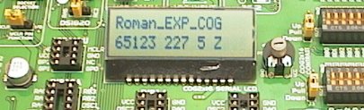
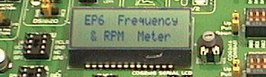
    I just used the COG LCD display example that came with the MikroC PRO compiler for the COG display driving. This is very easy to use. The frequency meter code is my own, I just setup the 2 timers, and did some calculating and formatting code so Freq and RPM can both be displayed.

    Special hardware...
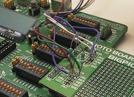
    I used a 555 timer oscillator connected to PORTC.F0. This is just a tiny PCB with a 555 timer and a pot to adjust the speed. This mimics the signal from an "engine" or machine etc so the project can display RPM. You don't need this, you can just press the RC0 button real fast!


    Adapting this code;
    I used the EasyPIC6 COG display because I was testing the new EasyPIC6 develoment board and the COG was the thing I wanted to test. However my simple source code will work fine with any normal text LCD. All you need to do to adapt it to your normal LCD is to setup your LCD as usual, and then change these LCD function names from;
    SPI_Lcd_Out(1,14,"Hz");
    to;
    Lcd_Out(1,14,"Hz");


    This .ZIP file contains the MikroC PRO source code in C, the project file, the autogenerated assembler .LST file;
    EP6_FREQ.zip


    EasyPIC6 Project 2. Accurate PWM signal generator - 12th Oct 2009.


    What is it?
    This project uses the built in PWM module in the PIC 16F887 (or 16F877). It generates an output signal with the PWM (pulse width modulation) adjustable over the entire 10bit range from 0 to 1023 (full).

    It can be used for driving DC motors to control their speed, or controlling lights (including LED lights) to control their brightness etc.


    Controls;
  • It has 6 buttons on PORTB (pressed = 5v);
    • PWM (fine) up/down (RB2/RB3)
    • PWM (coarse) up/down (RB4/RB5)
    • Change frequency; 3 output frequencies (RB6)
    • Display +/- PWM duty (RB7)
  • The output signal is on PORTC.F2
  • TMR2 is used at full resolution to generate the 10bit PWM
  • The COG text LCD shows this data;
    • It displays the frequency generated
    • It displays the Duty cycle as percentage; 0-100 %
    • It displays the PWM pulse width in 10bit counts; 0-1023
    • It displays the pulse width as microseconds; 0-?? uS


    Using it; This is actually a fairly sophisticated piece of test equipment. Apart from the limitation that it only has 3 selectable output frequencies, it is fully adjustable to 10bit PWM and is xtal locked so it can be used for a reliable PWM signal generator to drive power electronics and test drive DC motors etc.

    I wanted something my other signal generators don't do, and this PWM generator does it. The PWM pulse width (both high and low) is in actual microseconds and displayed as such. This is useful for testing inductors and developing switchmode power supplies. The finest PWM resolution is always 1 xtal period, see the following specs.

    For 8MHz xtal (standard EasyPIC6);
    Freq 7812 Hz, PWM resolution 0.125uS, pulse width 0-128 uS
    Freq 1953 Hz, PWM resolution 0.5uS, pulse width 0-512 uS
    Freq 488 Hz, PWM resolution 2uS, pulse width 0-2048 uS

    For 16MHz xtal;
    Freq 15625 Hz, PWM resolution 0.0625uS, pulse width 0-64 uS
    Freq 3906 Hz, PWM resolution 0.25uS, pulse width 0-256 uS
    Freq 977 Hz, PWM resolution 1.0uS, pulse width 0-1024 uS

    For 20MHz xtal;
    Freq 19531 Hz, PWM resolution 0.050uS, pulse width 0-51.2 uS (50 nanosecond resolution!)
    Freq 4883 Hz, PWM resolution 0.2uS, pulse width 0-204.8 uS
    Freq 1221 Hz, PWM resolution 0.8uS, pulse width 0-819.2 uS

    As it is important to know both the duty cycle and the pulse width when testing SMPS controllers I have provided a display option (via a button) that shows either the HIGH PWM and HIGH pulse width or the LOW PWM and LOW pulse width. This doesn't change the PWM itself it just shows the PWM data in 2 different ways.

    Procedure;
  • 10bit PWM is generated automatically by the PIC internal CCP1 PWM module
  • Every 0.25 second the 6 buttons are tested, PWM adjusted if pressed
  • Display is updated with new data if PWM was adjusted

    This .ZIP file contains the MikroC PRO source code in C, the project file, the autogenerated assembler .LST file;
    EP6_SIG_GEN.zip


    My EasyPIC port expander and COG routines - 12th Oct 2009.


    The above 2 projects use the MikroC PRO inbuilt functions to drive the port expander IC and the COG display on the EasyPIC6. If you don't have MikroC PRO (if you use other C compiler including the old MikroC) you can use my library of functions in the .ZIP file below.

    My EXP and COG LCD functions have a few advantages;
  • There are MUCH smaller than the MikroC PRO libraries
  • They will work on the old MikroC, and other compilers
  • They are open source, adapt them as you like
  • They can be converted to assembler or other languages

    My functions have these limitations;
  • They only contain the minimum that is needed to work the EasyPIC6 hardware


    Doesn't look any different right? Same easy COG LCD display driving, but using my smaller faster port expander and COG LCD routines.

    I compiled the simplest project to write some text to the COG LCD, using my routines and then again with the inbuilt MikroC PRO ones. They just wrote "Hello" to the LCD;

    My routines;
  • Works with older compilers
  • 213 ROM used (PIC 16F887)
  • 11 RAM used

    MikroC PRO inbuilt COG LCD libraries;
  • Must have MikroC PRO
  • 778 ROM used (PIC 16F887)
  • 17 RAM used

    I have to admit this is not a fair comparison. My routines only do the minimum to set the EasyPIC6 SPI port expander to be an output port, and the minimum to initialise the COG LCD and be able to move the cursor and write text to the LCD. Whereas the MikroC PRO routines use full SPI drivers to operate the SPI port expander IC and have more LCD routines giving more control of the COG LCD.

    These are the functions I provided;
    
    void RomanEXP_init(void);     // do first, inits EasyPIC6 SPI port expander IC
    void RomanEXP_lcd_init(void); // do next, inits the EasyPIC6 COG LCD
    
    void RomanEXP_lcd_move(unsigned char line, unsigned char col); // move LCD cursor
    void RomanEXP_Lcd_Char(unsigned char tchar);  // displays a text char on LCD (at cursor)
    void RomanEXP_Lcd_Out(unsigned char line, unsigned char col, unsigned char *text);  // display text string
    

    Note 1. There are a couple of other functions there that can send bytes to the port expander IC (to use the spare 8bit port) and also to send commands to the LCD. Generally though you only need to use the 5 functions above.

    Note 2. My functions address the LCD starting at ZERO. This is the standard for the Hitachi 44780 LCD chipset. Some other LCD functions have the address at 1. So with my functions, the top left LCD char is line0, column0 (not line1, col1).

    The .ZIP file below contains the two C files needed to use the code;
  • test_COG.c (is the LCD demo code)
  • RomanEXPCOG.c (is the file with my functions)
    You will need to create a project using MikroC or MikroC PRO for the test_COG.c file, and make sure both files are in the same directory.

    RomanEXPCOG.zip


    EasyPIC6 Project 3. PIC drives VGA monitor at 10 Megapixels/sec - 2nd Jan 2010.

    What is it?
    This is a test of generating VGA to directly drive a PC monitor from a cheap PIC. The 10 MIPS PIC is pushed near its limits doing this, the video data itself is generated by the PIC SPI module at 10 Megapixel/sec and is sent out RC5.


    It generates text of 27 chars x 16 lines, the VGA monitor is operated at 640x480 at 60Hz. Actual pixels at 10 Megapixels/second is 251 horiz pixels (243 are used), and vertical pixels are drawn double to give 240 scan lines. Text chars are 8x12 pixels. Each line of text is 12 pixel lines of the characters and 3 pixel lines (6 scan lines) black, which can be used as processing time.

    The colour is done by a simple DAC. Three pins on PORTD are used as "colour killers" and are toggled between high impedance and LOW which kills the RED, GREEN or BLUE respectively. They are independent of the luminance data that comes from RC5. Colour control is done before each scan line so the entire scan line must be drawn in the same colour. The colour was crudely sequenced by text line number, using 3 resistors as a crude 3-bit DAC. so each text line is drawn in a different colour (8 colours total). In proper use any text line could be drawn in any colour.


    This project turned out to be a lot more work than I expected! It didn't take long to get a rock solid Hsync and Vsync coded up, and to get something displayed on screen. But to get wall to wall text across the screen ties up every bit of the 25uS scan line (that is only 250 PIC instructions!) so all line processing etc has to be done in the Hsync pulse, a very full 38 PIC instruction period that must have zero jitter on both edges of the sync pulse.

    There is very little time for decoding text from character bytes to 12 bytes of pixel data and writing these to "video RAM" which is 12 simple blocks of RAM that can be "played" by the SPI module as the 25uS scan line occurs. I had to use lots of inline assembler pieces and some assembler jump tables and the code is pretty messy but it works. The clock is working as a demo but I haven't bothered implementing clock set buttons. The next step to make this useful as a text display device would be do hand code another 15 assembler chunks that decode character RAM data to the video RAM buffer so it can display 16 different lines of text, as at the moment it only decodes and displays one line of text repeated down the screen. It is a simple enough job but will require cut and pasting hundreds of lines of assembler and re-numerating into 16 variations so it will have to be a job for some other time...

    Anyway for proof of concept it works, the PIC SPI module can output pixels at 10 Megapixels / second with the PIC running at 10 MIPS. One problem I discovered was that the SPI module needs an extra PIC instruction every byte, so it always takes 9 clocks to send 8 pixels. For text use this is ok because I just used a 8 pixel wide font, and the blank pixel is between every text character. Obviously for a graphics display this would be a problem. I've heard that the SPI module has been updated on some of the newer PICs and they might not have this issue.


    The hardware is very simple. It only needs 3 resistors and some wires to a standard 15pin VGA connector. The pinout can be seen on the schematic above. Actually if you don't want the colour ability you can leave out the 3 resistors and ignore PORTD altogether, and just connect RC5 direct to one of the R G B pins for the very simplest wiring.


    With more resistors the "DAC" would have more bits and give much finer control of the text colour or even the background colour.

    Finishing it? I'd like to finish this up one rainy day as it would be handy to have 27x16 text VGA display using a cheap PIC like a 18F252 or 18F2520 etc. For the moment I won't release source code because it is big and messy but I have provided the .HEX file if anyone wants to replicate my VGA technicolour clock that has no clock set buttons. ;) It should work fine ony any of the EasyPIC dev boards (or a breadboard) as it just needs some simple connections to PORTC and PORTD.


    VGA_Test.zip


    EasyPIC6 Project 4. Serial storage CRO - 2nd Jan 2010.


    What is it?
    This project turns the EasyPIC6 into a digital storage CRO to display RS232 serial waveforms. The serial data is manually sampled at high speed on pin RC7 which is connected to the USART RS232 connector. This uses the touchpanel which is attached to the top of the GLCD so you can "touch" the buttons drawn on the GLCD.


    This is actually a copy of my BIGPIC6 project, but it has been ported to work on EasyPIC6 and 18F452 for people who don't own a BIGPIC6.


    Click HERE for the full project details!


    - end -

    [Back to Home Page]