[Back to Home Page]
www.RomanBlack.com
DC motor crystal clockwork!
A system for driving a cheap DC motor very slowly, and very accurately
- 8th April 2013.
What is it?
This is a very simple way to use a cheap PIC to run a DC motor at a very
slow speed, and for that speed to have very high accuracy.
This can do tasks that were previously done using a stepper motor;
* Silent clock movements
* Telescope driving
* Solar array tracking
* Video camera track movement
It gives these benefits;
* Uses much less power, and is quieter/smoother than a stepper motor
* Motor speed is locked to a crystal, keeps "clock" time accuracy
* Motor speed is adjustable in incredibly fine steps (parts per billion)
* Motor speed can be VERY slow (less gearing needed)
* Auto-recovers speed and position after being bumped
* Very simple driving electronics (no stepper driver needed)
How it works
The main goal of this was to replace stepper motors in precise
clock-movement type applications. Unlike a stepper motor, a DC motor might
speed up or slow down in response to short term load events,
(ie; a few degrees or fractions of a second) so the main focus was on
making the average speed perfect.
To maintain a perfect average speed the PIC generates a reference frequency
using a Bresenham math algorithm (similar to the systems on my page
here.)
That has the benefit of being able to make any perfect average frequency,
(which sets the motor speed) from any xtal value. It is also adjustable in
incredibly fine steps, so it can be "tweaked" to make highly accurate clocks
and telescope tracking.
Then the motor speed is recorded using a quadrature encoder mounted on
the motor shaft. Many DC motors on ebay etc come with quadrature encoders
already attached, but I just glued on a disc and sensor from an old PC
"ball" mouse;

The big benefit of a quadrature encoder in this app is that it cannot
lose count of the motor position, so even if the motor is bumped or jerked
forward OR backward by some load force the whole system will just "catch up"
afterward and still give perfect average motor speed.
The reference frequency is used to count forward and makes a "reference position".
This count is constantly compared to the motor position, and if the motor
lags behind the reference then PWM is increased.
I developed a similar system in 2011 for my "Pulse Counting Loop" algorithm, for
mains synced clocks. This is similar
in some ways to a "Phase Locked Loop" but is better as it can repair itself
and recover perfect timing even after being out of phase by thousands
of cycles.

(See above) By the time the motor has lagged about 10 encoder counts the PWM will reach
max, so the difference between the "perfect" reference position and where
the motor is at any time will generally only be a couple of encoder counts
(a few degrees).
The system works very well! The digital system used to record the reference
and motor position maintains a perfect average speed (as perfect as your
xtal). Likewise it can be better than a stepper motor as it uses much less
current, doesn't have the harsh vibration, and any short term over-driving or
backdriving error is accounted for and will be fully corrected right
after the fault is finished.
The algorithm as C code
Everything for motor movement is handled in a timer interrupt. This makes
it very easy to use, just put the interrupt in your PIC C code and set one number
to the speed you want, then the motor will run automatically;
// This constant sets the motor speed. The value is in nanoSeconds per pulse,
// as we are using a quadrature encoder there are 4 pulses per encoder slot.
// Example; 1 motor rev per second = 144 pulses /sec.
// nS per pulse = 1 billion / 144 = 6944444
//#define  MOTOR_PULSE_PERIOD  3472222    // 2 RPS
//#define  MOTOR_PULSE_PERIOD  6944444    // 1 RPS
#define  MOTOR_PULSE_PERIOD  13888889   // 0.5 RPS


//+++++++++++++++++++++++++++++++++++++++++++++++++++++++++++++++++++++++++++++
void interrupt()
{
  //-------------------------------------------------------
  // This is TMR0 int, prescaled at 2:1 so we get here every 512 instructions.
  // This int does the entire closed loop speed control;
  //  1. updates encoder to see if motor has moved, records it position
  //  2. updates reference freq generator, records its position
  //  3. compares the two, sets PWM if motor lags behind reference
  //  4. limit both counts, so they never roll, but still retain all error
  //-------------------------------------------------------
  // clear int flag straight away to give max safe time
  INTCON.T0IF = 0;

  //  1. updates encoder to see if motor has moved, records it position
  enc_new = (PORTA & 0b00000011);   // get the 2 encoder bits
  if(enc_new != enc_last)
  {
    if(enc_new.F1 != enc_last.F0) mpos++;   // record new motor position
    else                          mpos--;
    enc_last = enc_new;
  }

  //  2. updates reference freq generator, records its position
  bres += 102400;                 // add nS per interrupt period (512 insts * 200nS)
  if(bres >= MOTOR_PULSE_PERIOD)  // if reached a new reference step
  {
    bres -= MOTOR_PULSE_PERIOD;
    rpos++;                       // record new xtal-locked reference position
  }

  //  3. compares the two, set PWM% if motor lags behind reference
  if(mpos < rpos)   // if motor lagging behind
  {
    mlag = (rpos - mpos);                            // find how far it's lagging behind
    if(mlag >= (100/MOTOR_PROP_GAIN)) CCPR1L = 100;  // full power if is too far behind
    else CCPR1L = (mlag * MOTOR_PROP_GAIN);          // else adjust PWM if slightly behind
  }
  else            // else if motor is fast, cut all power!
  {
    CCPR1L = 0;
  }

  //  4. limit both counts, so they never roll, but still retain all error
  if(rpos>250 || mpos>250)
  {
    rpos -= 50;
    mpos -= 50;
  }

}
//+++++++++++++++++++++++++++++++++++++++++++++++++++++++++++++++++++++++++++++
My test setup
I found a small DC motor in my junkbox. This one is a 12v motor from
a CD or DVD player. It originally had a tiny pulley and belt and was
used to slide the CD drawer in and out. These 12v motors are made for
reasonably low RPM use, which is a good choice for this app. A 12v low speed
motor will work better here than a 3v high speed motor!
Testing the motor.
I ran the motor from regulated 5v and it worked fine, and was quite energy
efficient using only about 100mA no load. The next step was to hook up a
driver transistor and run PWM to the motor to control its speed...
Motor RPM at 5v and different PWM duty %;
5v PWM 40%, RPM = 434
5v PWM 60%, RPM = 786
5v PWM 80%, RPM = 1138
5v PWM 100%, RPM = 1460
I also tested the stall speed of the motor. The motor would not run
any slower than approx 70 RPM.
The encoder.
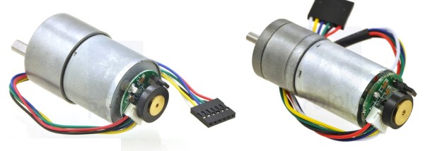
I have DC motors with quadrature encoders already attached, like these
common examples;
But instead I wanted to show how you can just add an encoder to any motor,
and I wanted to test a motor with no gearing. The 36-slot encoder wheel
came out of an old Microsoft Mouse, as did the sensor electronics. I just
cut through the original mouse PCB and soldered 4 wires direct to the pins
of the opto devices.
The optos are extremely simple and are just an InfraRed LED on one side of
the slotted disc, and a dual photo diode on the other side of the disc.
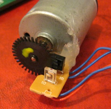
I glued the sensor PCB to the motor with a blob of hot melt glue, making
sure it was in the right position (same as how it was in the mouse).
The 36 slots and two photo sensors are run in "quadrature" mode, so
it gives total pulses of 144 per revolution (36 * 4).
It only takes 3 resistors to interface the quadrature encoder sensor
to the PIC; a 1k series resistor for the IR LED, and two bias resistors for the
dual photo diodes. I used 20k trimpots for those two bias resistors, as that
makes it easy to adjust the biasing to give a nice 50:50 duty of the
signals into the PIC digital input pins. (Quadrature encoders work best
if both signals are squarewaves with 50:50 duty).

Above you can see my 'scope capture of the encoder waveform from one of
the encoder's photodiode sensors (bottom in blue),
and how the PIC Schmidt Trigger input sees it (top in yellow). The motor was
running a bit over 4 revs per second, at this speed the photodiode wave looks
like a sine. At slower speeds the photodiode wave looks more "digital".
I got the PIC to output on two spare digital output pins what it
actually "sees" on its Schmidt Trigger encoder inputs. This is a
handy trick that lets you bias the encoder photodiodes to give good
50:50 duty.

Above shows the pair of encoder inputs as the PIC sees them. They are
not absolutely perfect in terms of 50:50 duty or phase, but this
is quite ok for such a small cheap sensor that was glued together. :)
Motor driver electronics.
To show how simple it can be done I just used a single transistor to
drive the motor with PWM. No IC's needed.
As this motor only needed <200mA I just used a tiny BC337
transistor which is good for 500mA continuous and 1A pulsed. The PIC
PWM digital output pin drives the transistor base through a simple 560
ohm resistor. On a larger motor you would use a larger NPN transistor
or better still, an N-channel FET.
The only other part needed was a back-EMF diode across the motor,
I just used a tiny 1N4148 diode as this is a very small motor <200mA.
With a larger motor < 1A you would use a 1N5819 schottky diode,
or on a big motor of multiple amps you could use a T0-220 pack
schottky diode (both the diode and FET must be rated for average
motor current).

I controlled the motor from my EasyPIC6 development board. All the
encoder hardware and PWM driver transistor etc are shown here.
Apart from the PIC and its xtal, there are only a few parts needed.
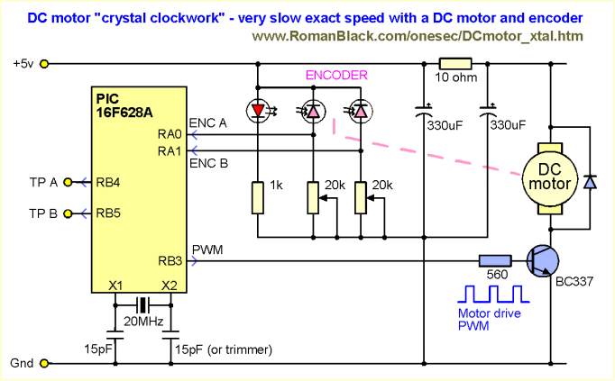
Above is the entire schematic of my test setup, you can see how simple it is.
Even with the added complexity of a quadrature encoder there are
still very few parts with the PIC (and software!) doing all the
clever work.
Notes on the schematic.
The PIC digital outputs TPA and TPB echo the two quadrature encoder signals.
You can connect a 'scope to these 2 points and adjust the trimpots to
get good 50:50 encoder sensor duty cycle. Once the system is set up these
pins are no longer needed.
I used a tiny NPN transistor to drive the motor as my motor only needed
a handful of mA. For a larger motor you could use a NFET as the motor
PWM driver, and a large Schottky diode across the motor. You could also use
a motor-driver h-bridge IC, especially if you wanted to run the motor in
either direction (for track/return in solar panel tracking).
As my motor was tiny I chose to run it from the same regulated 5v supply
as the PIC. For that reason the schematic has an extra 330uF cap and a
10 ohm resistor.
These two parts stop any noise from the motor PWM from interfering with
the encoder signals, and also allowed me to easily measure the average
motor current consumption by measuring the voltage drop across the
resistor. In most cases you would run a separate power supply for the
motor (especially for large motors!) so these two parts are probably
not needed.
Movie
Here is a short movie of the ungeared DC motor doing 0.5 revs per second (30 RPM)
nice and smoothly. :) I put a blob of yellow paint on the disc so you can
see it rotating.
Click for Movie (6.90 Mb)
Energy efficiency!
This was a very pleasant surprise! With the DC motor (ungeared) doing
exactly 1 rev per second and no load, the entire motor power consumption
was 5v at 4mA! The PIC and the encoder LED consumed more power than that!
Even with moderate load on the motor the power was still under 5v 20mA.
For lightly loaded systems with high gearing (clocks or solar trackers etc)
this is many times less power consumption than even a tiny stepper motor.
Downloads
The download ZIP file contains the fully tested PIC MikroC source code,
the HEX file for a PIC16F628A, and a couple of schematic diagrams etc.
Download DCmotor_xtal.ZIP file
Limitations of my code
The code supplied needs the interrupt to happen a few times faster
than the encoder pulses, when the motor is doing the set speed.
That allows the encoder to still track situations where the motor might
run at 4 times faster than the set speed (like being bumped etc).
So my PIC 16F628A 20MHz code above is limited to a max encoder speed of about
2500 Hz. (Note! At 1 rev per second my example was running at 144 Hz).
Going to a PIC 18F could double that 2500 Hz, and there are ways the code
could be optimised for speed to make it significantly faster again.
I have not bothered with that as the main point of this system is to run
the motor at an exact SLOW speed. If you need to run the motor at an exact
fast speed one easy option is to reduce the number of slots on the encoder
disk, and with a minimum 1 slot disc it will make 4 pulses per motor rev,
allowing a motor speed of 2500/4 = 625 revs/sec or 37500 RPM!
Very slow motor speeds
The DC motor I was using was a nice low-RPM motor type, tested at only
1460 RPM at 5v. Motors designed for low-RPM use will be much more stable
if you need very low RPM drive like this.
I had no trouble running this motor smoothly at 1 rev per second
(60 RPM), and it even worked pretty good at 0.5 revs per second (30 RPM).
Note; both these speeds were below the 70 RPM stall speed of the motor!
(see video above).
Running a DC motor near or below its stall speed.
DC motors have strong springy magnetic "detents", caused by
the permanent magnet stator pulling at the iron in the armature.
Small DC motors often have 3 or 6 obvious detents per rotation, if you
turn the motor by hand.
If the PWM (or the average motor voltage) gets low enough the motor
will just stop rotating, a situation called "stall".
For this reason, it is almost impossible to rotate the motor smoothly
at speeds below the stall speed.
To run the motor at those low speeds requires some type of PWM cycling
where the PWM is high enough to make the motor move a few degrees, then
PWM needs to be lowered or cut so the motor does not run too fast.
This is repeated in a very fast cycle and with the benefit of some
rotating inertia the overall rotation can be smooth (or smooth enough)
and a very low RPM can be achieved.
The system described here will give this effect automatically, and
maintain the exact average motor speed. Whether the motor turns smoothly
at the exact speed, or moves with twitches or jumps at the exact average
speed, is determined by a number of factors.
How to get very low RPM from a permanent magnet DC motor
1. Use a geared motor. OK, this one is cheating. :) More gearing
means the motor can be run above it's stall speed and still get the final
shaft turning at very low RPM. Fortunately most DC motors with encoders
you can buy from hobby suppliers also have gearboxes on the motor.
2. Add more constant load to the motor. Adding load means more PWM
is applied making the torque more stable, and likewise the load will dampen
tendencies for the rotation to jump around. Even driving a gearbox
can be enough load to damp the motor and give smooth rotation. (This is the
first thing to check if your motor is jumping around, just let a fingertip
drag lightly on the spinning shaft and it will probably stabilise.)
3. Use a low-RPM motor. Some motors run better at low speeds than others!
Some testing can be very helpful. Generally 12v and 24v motors can be run
slower than 3v and 6v motors. Larger motors (especially larger diameters)
usually are more stable at lower RPMs.
4. Use a finer encoder with more pulses per rev. An encoder with more
slots runs the closed loop system more times per rev so will be more stable at
lower RPM. With less slots you will need to run the motor faster,
or tolerate some jumpiness in the rotation (average speed will still be perfect).
5. Add flywheel inertia to the motor. A flywheel or weighted disc
directly on the motor shaft can help make the motor rotation more stable.
6. Reduce the PWM frequency. Lower frequency PWM will reduce the
stall speed as the motor will tend to move in tiny pulses. My software
uses PWM at 3125 Hz but commercial traction drivers using DC motors can
run as low as a couple hundred Hz.
7. Tune the gain in my software. The proportional gain
(how many encoder pulses lag does it take to go from 0-100% PWM)
can be adjusted in software. I found a gain of about 10 steps worked
well, so PWM would oscillate between 20,30,40% to maintain the
correct speed, and that was enough torque ripple to avoid stall which
would occur if the PWM was say at a constant 24%.
- end -
[Back to Home Page]