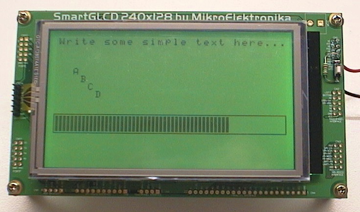
It draws some graphics boxes at XY pixel coords (240x128 grid).
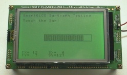
The variable called barlength shows how easy it is to make a useful
screen object, in this case it is a display bargraph where the length of
the bar inside is controlled by the variable.
Download SG02_Simple_LCD.zip
Tut03 - Using the TouchPanel
This program introduces some very simple fast functions I created to
read the touchpanel XY coords of where it was touched.
Although MikroC PRO already has inbuilt touchpanel functions, MikroC does not.
Also, I wanted some functions that were very fast so they could read the
touchpanel during time critical PIC applications. Reducing the touchpanel
functions to the simplest and fastest code also makes them very easy to
understand.
These functions only read either X or Y from the touchpanel at a time,
so to get an XY coord you need to test both. However for some fast applications
where the PIC may be very busy and all you need is a "STOP" button on the
GLCD, you may only need to test X or Y, not both. Also to speed things up
you can test X or Y at separate times with your important PIC code running
in the middle.
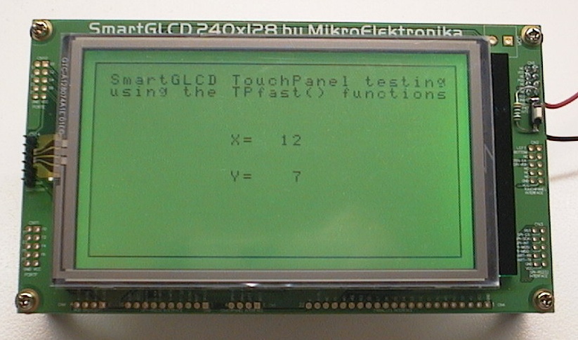
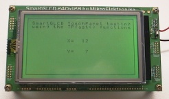
This program tests the touchpanel X and Y continuously, and displays X and
Y on the screen. The X and Y values range from 0-255 and are simple ADC
values from the resistive touchpanel, they have not been calibrated to
become exact pixel coordinates.
Download SG03_Touch.zip
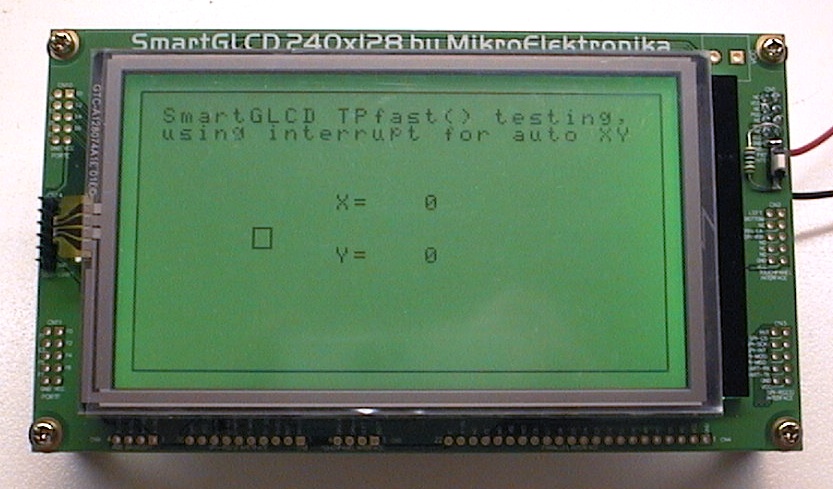
Tut04 - Using the TouchPanel in an interrupt
This program also uses my stripped-down TPfast() functions, but this time
the touchpanel is handled completely automatically in a timer interrupt.
The TPfast() touchpanel functions have been moved into their own file called
TPfast.C, this is explained in the source code.

The timer interrupt executes very quickly so it does not steal very much time
from your other processes, and it sequentially reads the X and Y from the
touchpanel each time the interrupt occurs. Also, if the touchpanel is not
touched it sets both X and Y to zero, as a very easy indicator your code
can use to know if the panel is touched.
The display shows the X Y coords (if the touchpanel is touched) otherwise
they are shown as 0 0. There is also a tiny graphic indicator box that
goes black if the touchpanel is touched.
The XY coords are still simple ADC coords 0-255 from the resistive
touchpanel hardware.
Note! There is a simple variable called tp_xy_locked that will
lock the XY values at their current state so the interrupt cannot change them.
This allows you to work with those values as long as you wish; process them,
display them etc and they will not change. Then just unlock the values and
the interrupt will update them with the latest touchpanel coords automatically.
Download SG04_Touch_Int.zip
Tut05 - Making an interactive bargraph control
This program gets the touchpanel and GLCD working together to make a very
simple interactive screen object or "virtual control".
The control is a bargraph or bar slider. It can be touched with a
stylus or finger and sets the bargraph to the length where it was touched.
This is one of the most useful screen controls for adjusting parameters.
This project introduces a new function TP_convert_XY that converts the
touchpanel XY ADC values to actual screen pixel XY coords. This is useful
because it tells the exact place where the user touched the screen, and
then it is easy to determine where the user touched the control (the bargraph)
because both are specified in screen pixel XY coords.
Then the bargraph is set to the new position as touched by the user.
The screen shows the simple ADC XY coords directly from the resistive touchpanel
hardware (shown as TX and TY) and also shows the screen pixel XY coords
that were produced from calculation (shown as SX and SY). It also shows the
bargraph of course.
The source code is a bit crude (for simplicity) but the bargraph is defined
with its position and size that can easily be changed and the code should
easily be adaptable to bargraphs of different sizes.
Download SG05_Bargraph.zip
Tut06 - A 3-bargraph RGB LED PWM controller
This program uses 3 interactive bargraph virtual controls to set the
PWM (brightness) of each of the backlight RGB LEDs. This will let you
set the screen to any colour you like, including dimming the backlight for
power savings. Each RGB LED can be set to a brightness in the range 0-255
giving true 24-bit colour control (16 milion colours).
The LED PWM is done in a timer interrupt and is fast and simple,
and being timer locked it makes a stable and accurate PWM at about
280 Hz.
As a useful application it could be used as a RGB room light controller
for an entertainment room using the new high power RGB light fittings.
In this case the RGB backlight LED connections are already brought out to
connector CN9 on the SmartGLCD board, so you could connect that to your RGB
lighting driver, assuming it accepts logic level PWM signals.
As a lighting controller the SmartGLCD will also dim its own display to match
the room lights brightness and colour, a nice feature in a dark entertainment
room.
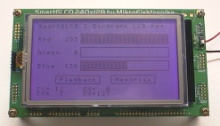
The display screen shows the 3 bargraphs for RED GREEN and BLUE, and also
the actual PWM value used (0-255 range). There is a simple "memorise"
and "playback" that demonstrates how easy it is to remember a user
setting for the lighting. Obviously the display layout could be made more
tidy and some more features added if this was to be used as a lighting
controller but all the basic features are implemented so it should not be
too hard to adapt to your needs.
Download SG06_LED_PWM.zip
SmartGLCD tips and tricks!
Adding a reset button!
This only took me about 2 minutes and I am so glad that it is there now!
A reset button is extremely handy for testing code while doing development.
Although a finished project might not really need a reset button I really
recommend you do this mod on your development SmartGLCD.
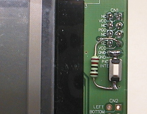
All that is required is a small pushbutton and a 220 ohm resistor.
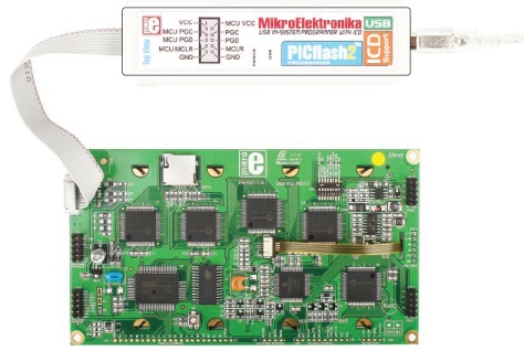
The pushbutton and series resistor go between pin 7 of the ICSP connector
CN1 and ground (pins 9 and 10). See the photo above for how I wired it.
Note! Pin 7 of the connector is labelled "Vcc" which should have been
labeled "MCLR" or "Vpp". Either way it is connected to the MCLR reset
pin of the PIC. Using a 220 ohm series resistor means that it cannot
hurt any programmer that may also be connected to the SmartGLCD and
it is safe to press the reset button at any time.
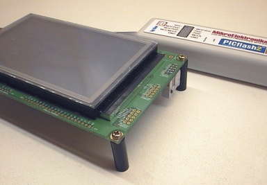
Adding some PCB standoffs (legs)
I screwed four PCB standoffs onto my SmartGLCD to lift it up.
Now it no longer rocks around on the connectors etc when I press the
touchpanel. I used 25mm standoffs but 20mm are probably the best size.
Anything less than 20mm may not let you use the PICflash2 programmer
as it has an 18mm tall plug!
Software tricks - Keeping the original HEX code
I read the original demo HEX code that was in the SmartGLCD and put it
here.
The bootloader HEX file is also
available from MikroE, the bootloader (alone) is
here.
It can be very handy, for example when I had a GLCD initiaise bug
my SmartGLCD seemed to stop working, but programming the original HEX
code back into the SmartGLCD brought it back to life and proved the hardware
was fine. Warning! You can't program this HEX code using the bootloader as
it contains a bootloader, you can only program it with an ICSP programmer.
If you are using a bootloader and need a test HEX code to check your
SmartGLCD please use any HEX file from any of my tutorial projects above.
Initialising the GLCD right!
The GLCD has its own controller chip which is also a microcontroller.
If it intiialises wrong you can get some weird symptoms! The MikroC function
always initialises the GLCD properly, however if there is any delay between
powering up the SmartGLCD module where its pins are left floating before
calling the initialise function the GLCD can fail to initialise.
This delay can include boot up code etc.
Fortunately this is easy enough to fix, just make sure the following lines
are in your source code as one of the first things the PIC does. It holds all
the PORTJ pins low which keeps the GLCD controller IC in reset and with its
control pins in a defined state while the PIC does any boot up code including
delays. Then the GLCD should always initialise properly.
Note! The T6963C GLCD datasheet says the display should not be held in reset
for long periods as it may put DC on the display crystal and cause it to
deteriorate. It's wise to run T6963C_Init() fairly quickly after doing
the following code;
  LATJ  = 0b00000000;   // Keep GLCD in reset
  TRISJ = 0b00000000;   // GLCD control port
Advanced Tutorials!
The following tutorials assume you have got up to speed now with your
SmartGLCD and you are confident enough to try some difficult projects...
Please don't contact me for tech support with these projects, generally
they were tested before being put up here but there may be some issues
with using these, so you are welcome to use my code but you might need
to think a bit. :)
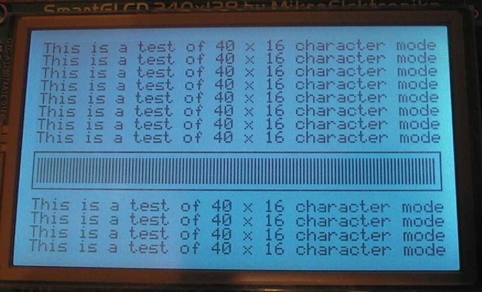
Tut07 - Using 40x16 text mode!
Well this one is not that difficult, but it is extremely useful!
Normally the GLCD is run with text mode "wide" font of 8x8 pixels and a text
display size of 30x16 characters to fill the screen.
This project
puts the GLCD in "narrow" text mode of 6x8 pixels, so the GLCD now displays
40x16 characters which is a massive improvement in display power, and because
the characters are identical it now looks much better as the characters now
have correct spacing as you would see on a 16x2 typical text LCD.
This project was very easy as the MikroC graphics functions seem to work
seamlessly with the new GLCD narrow font mode, so that's a credit to the
MikroC compiler. However even though the line and rect functions work ok
there will probably be issues with drawing images or icon images to the GLCD
because the graphic RAM addressing is now in bytes of 6 pixels wide (not 8).
So this is now in the advanced tutorials, it all seems to work great but you
might need to mess around a bit if you need to draw images to the screen.
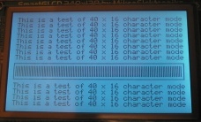
The GLCD is initialised in 40x16 text mode, then it shows text lines of
40 chars wide which worked ok with the MikroC function. Also, a simple
graphics object was drawn across the screen to check that addressing and
graphics were still working ok.
To initialise in 40x16 narrow font mode you need to set the FS bit (bit6 on
PORTJ) and then set the graphics addressing width to 6 in T6963C_Init().
See the code, it's pretty easy.
This project also uses my simple RGB LED PWM system in the timer0 interrupt,
to set the RGB backlight LED to any colour.
Note! I will probably be using 40x16 text node from now on in my future
tutorials as it is a big improvement in the ability of the display!
Download SG07_40x16.zip
Tut08 - Making it draw FAST!
Note! Firstly I want to say that the MikroC compiler functions for
the T6963C GLCD are very nice, and do their job well!
But because they are designed to cover all
sorts of setups and situations they are not optimised for speed. Instead
they are optimised for plug-n-play, ie; they will work on many different
development platforms and different PICs etc.
This project is my first crude attempt to make the GLCD work FAST.
The goal was to strip everything to the bone and see what it can do.
I noticed on my previous tutorials and the MikroE SmartGLCD demo that it drew
text fast to the GLCD but seemed a bit slow to draw some graphic objects,
mainly filled boxes.
After examination of the MikroC functions, it seemed that every
graphic drawing function uses the Line() function, and the Line function
draws only one pixel at a time, and because it is capable of drawing
diagonal lines, every single pixel draw requires a 16bit multiply and
16bit divide! This is necessary for diagonal lines but is terribly slow for
drawing horizontal and vertical lines which are the most common and are
also used to draw all the screen objects like rectangles and filled boxes.
Basically, to draw a filled box the MikroC functions draw the entire
filled box with single pixels and every pixel uses lengthy math code!
Making optimised systems to draw horizontal and vertical lines.
This should not be too hard. The GLCD has graphic RAM in horizontal rows,
so it should be possible to write "black" bytes in sequence to make a fast
horizontal black line. The start and end of the line might need a bit of fuss
but the bulk of the line can be drawn VERY fast. Vertical lines will be many
times slower as they must be drawn one pixel at a time.
Optimising the commands directly to the GLCD
After reading the GLCD T6963C datasheet, it looks like every command to the GLCD
takes either 1, 2 or 3 bytes. The MikroC functions for sending these commands
are designed to allow multiple development hardware and different PICs and PIC
pins etc. This meant a lot of overhead, and after removing this overhead and
making new command functions that were ONLY for the SmartGLCD hardware and it's
PIC pins, I was able to speed these commands up twice as fast.
I used Timer1 set to exact uS to time how long it took to draw the
objects to screen, and displayed the time on screen.
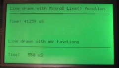
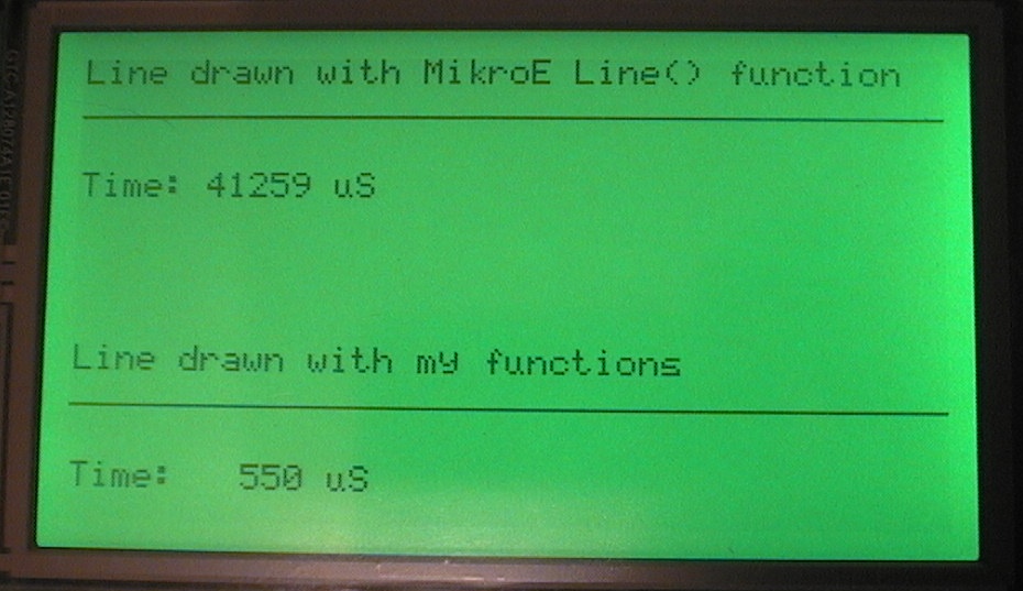
Horizontal line test results.
The first test result was pretty impressive! The MikroC Line function takes
41199 uS to draw a line of 240 pixels right across the screen. My test of drawing
bytes filled with 6 "black" pixels directly to graphics RAM took only 548 uS,
which was about 75 times faster! However I do want to state that my test was a
best possible case with no coordinate processing (I told it the exact graphic
RAM loacation to start) and with the line being fully byte-aligned so there
was no messing with pixel alignment at the start or end of the line.
A proper horizontal line function would have some coordinate processing and some
bit processing at the start and end of the line, so it would be quite a bit
slower, maybe 3 to 5 times slower.
But it does show that it is possible to draw objects very fast to the screen and
raises possibilities of making optimised functions to draw rectangles and
especially filled boxes that can be drawn from black horizontal lines.
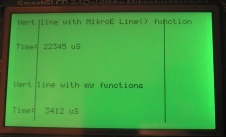
Vertical line test results.
The MikroC vertical line function ran at
a similar speed per pixel and took 22345 uS to draw a vertical line of 128 pixels.
My manual system had to re-address every byte, then draw a single pixel, and
it took 3410 uS to draw 128 vertical pixels. That was about 6.5 times faster
than the MikroC Line function.
At this point it looks like these fast graphic functions might be worth
refining into functions that are easier to use and still be quite a bit faster
on the SmartGLCD than the standard compiler graphics functions. A power-user
who needs very fast GLCD speed could even work with these functions as they are
and manually access the graphics RAM. These functions should also be excellent
for drawing graphics images, icons etc to the screen especially if they are
byte-aligned.
But for most SmartGLCD users the standard graphics functions in the MikroC
compiler are very easy to use and will allow fast practical code development!
And of course if using the development software MikroElektronika Visual GLCD
for Windows it generates all the GLCD buttons etc as source code so you would
be working with the standard compiler graphics functions there too.
That's why these fast graphics functions remain in the advanced section
of my tutorials page... They CAN be very fast if you go to the hassle of
making them do what you want. Use them at you own risk! ;)
Download SG08_Fast_GLCD.zip
Tut09 - Custom text characters
The MikroC compiler and examples didn't seem to have any support for making
custom text characters, so I had a go at it. :)
Reading the
Toshiba T6963C GLCD datasheet
was painful but paid off with
some information. To use custom text characters you tell it a RAM block
to be used (RAM blcoks are 2048 bytes) then the custom characters can be
stored in the last half of that RAM block (last 1024 bytes) as 128 custom
text characters which are each made by 8 bytes of horizontal pixels.
In this case the characters 0-127 are the standard text characters
(called internal CG) and the characters 128-255 are your custom text
characters.
Note! The MikroC functions to write text to the screen use an offset
of -32 which is necessary to make an ascii character like SPACE convert
to the correct CG address of 0. Because the MikroC functions do a -32
offset you can use the standard ascii characters which are 32-159, and
your new custom characters are offsetted -32 so they are now
160-255 range followed by 0-31.
This is a little annoying but it is covered in my source
code and it works fine, you still get all 128 custom text characters and
(of course) the standard 128 internal ascii characters.
The T6963C also has a "external GC mode" which is supposed to allow you
to use a full 256 custom characters instead of the internal CG characters.
Unfortunately I could not get this to work in my first attempts, I think
it might be because I am using the MikroC functions to communicate with
the GLCD and these functions may be forcing the GLCD to the standard
"internal CG mode".
Anyway my source code here gives you 128 working custom text chars.
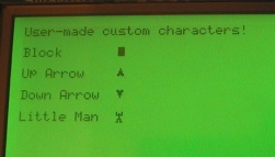
The screen above shows the 4 custom characters that were made
and then displayed to GLCD using the standard text functions.
After the annoying Toshiba T6963C datasheet deciphering it worked out being
quite simple and easy to make the custom characters, and it is
super-easy to display them as you just use the standard MikroC
T6963C_Write_Text() and T6963C_Write_Char() functions.
Note!! One thing I did notice with the CG RAM is that it is
very retentive! Even with all power plugs removed from the SmartGLCD
for a full 3 minutes, when power was re-applied the RAM had its
memory perfectly intact. This is because the GLCD RAM chip goes into micropower
mode when shut down, and lives off one of the capacitors on the SmartGLCD
board. This might be good or bad, but just remember if you want the CG RAM to
be reset (or to change at all!) then you need to actually write to it.
Download SG09_Adv_Text.zip
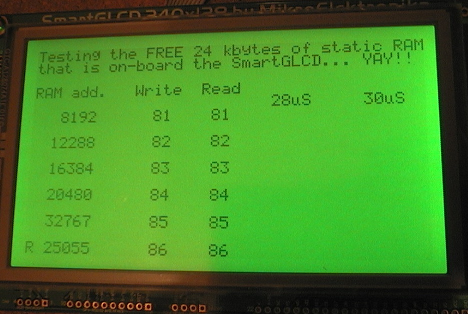
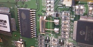
Tut10 - Massive static RAM for free!
Wow! This one of those finds that makes your eyes pop. I was reading up on the
T6963C GLCD driver IC, and the other ICs on board the SmartGLCD. I found there
is a LY62256 (32 kbyte) static RAM IC that is used by the T6963C GLCD controller.
As the T6963C controller is capable of addressing 64k of RAM, it has been fully
connected (I checked the tracks) so the T6963C has access to 32 kbytes of RAM!
Above shows the LY62256 32kbyte static RAM chip on the bottom of the SmartGLCD.
The RAM usage by the GLCD (with 40x16 text mode and 240x128 graphics mode) looks like this;
0 - 5119 (5120 bytes; graphics RAM, 40 bytes across, 128 bytes down)
5120 - 5759 (640 bytes; text RAM, 40 chars across, 16 lines down)
5760 - 6143 (384 bytes; spare?)
6144 - 8191 (2048 bytes; normally spare, but I use for 128 custom text chars CG RAM)
8192 - 32767 (24576 bytes; totally free for your enjoyment)
This is amazing! There is 24k (maybe 26+k) of totally free, nice fast static
RAM at your fingertips. For years I have been hinting that MikroE should
put a nice big static RAM on their BigPIC development boards and now they
finally did it and didn't tell me... ;)
Accessing the static RAM.
The MikroC functions do not include any functions for READING from the
T6963C GLCD controller or from its static RAM. As I had already written my own
very fast functions to write data and commands to the GLCD it was easy to write
one more function that reads a data byte from the GLCD (which it gets from its
static RAM chip).
Writing to the static RAM;
1. Send the 16bit address to the GLCD, and a "set address" command
2. Send the data byte to the GLCD, and a "write byte" command
Reading from the static RAM;
1. Send the 16bit address to the GLCD, and a "set address" command
2. Send a "read byte"command, then read the byte from the data port
There are some shortcuts, like writing and reading sequential bytes can be
used with the same auto-increment shortcuts as used for writing to graphics
RAM to display things. There is also a block mode, as used for writing graphics,
it can be used for fast writing and reading to the static RAM.
My functions are optimised for the SmartGLCD hardware for speed, so even
including the overhead of sending the 16bit address it only takes about 28uS to write
a byte to RAM and about 30uS to read a byte from RAM. If you are doing sequential
writes or reads to RAM (using auto increment address) it is about 2.5 times faster
than that (around 12uS per byte), and block writes and reads can be about
5 times faster (about 7uS per byte).
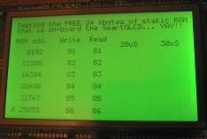
The screen above shows 5 RAM addresses from 8192 to 32767 all being constantly written
to and read back, if there is any failure there is an "ERROR!" text tag that will
appear. The bottom line shows a "random" address that is also tested the same way,
the random RAM address is changed every time but is always between 8192 and 32767
(it is always in the top 24k of RAM).
The 2 time fields show in actual uS the amount of time to set address and write a byte
and to set address and read a byte.
Please don't be afraid to use this RAM! This is a very powerful resource on
your SmartGLCD and it is easy and reliable to use. It is just as easy as
writing to the GLCD graphics ram, except of course nothing is shown on the
screen. ;)
Note! Just be aware if anything writes text or graphics to the GLCD the
RAM address will have been changed (of course), so you need to set the address
again to read or write a byte in the RAM.
Note 2! One thing I did notice with the static RAM is that it is
very retentive! Even with all power plugs removed from the SmartGLCD
for a full 3 minutes, when power was re-applied the RAM had its
memory perfectly intact. This might be good or bad, but just remember
if you want the static RAM to change then you need to actually write to it.
Download SG10_Free_RAM.zip
Tut11 - Big Digits
Having lots of text (ie 40x16 chars) on screen is great, but I also wanted
the ability to display larger digits that can be seen from a distance, which
will make the SmartGLCD good for instrument applications, like a frequency meter or
as a wall mounted display.
The T6963C GLCD driver only has one inbuilt font, the standard 6x8 font
(same font can also be displayed as 8x8 with extra blank pixels). I considered
using graphics sprites as large characters, but soon realised that it would be
better to use custom text characters as they draw to the screen 8 times faster.
It also means the large font characters are stored in the GLCD RAM and
the GLCD controller does all the work of displaying them, a nice type of
simplicity. This turned out to work very well, because I had already found
out in Tutorial 09 that custom text characters were easy to do. It also allows
text overlay as XOR etc, same as the normal sized text characters.

Above is the bitmap I made and used to generate the big font data table, the digits
are standard style LCD type 5x7 digits but doubled in size so they are actual
10x14 pixels then one pixel space added all around to make 12x16. Once the
digits were 12x16 they were easily separated into 4 custom text characters
of 6x8 pixels each (as a 2x2 character block).
Because there are 128 custom text chars the max digits you can make this way is
128/4 or 32 digits. I settled for the numerals 0-9 and some other characters to
display volts, amps, watts, temperature C and F etc. That should be enough to
make some useful displays. It's a total of 19 characters.
Using the big digits is very easy, you can use them the same way as the MikroC
functions to draw a character or character string to the screen. And they are very
fast so you can do a display that is rapidly changing and it still looks very clean
drawing to the screen.
Just #include the file "SGBigNumbers.c" and you can use the large numbers in your
own projects with the functions I have provided.
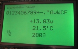
The screen above shows the normal sized digits at the top, then the new double-sized
big digits. Then a couple of sample displays. You can see from the C source code
it is extremely easy to use the big digits. There is a 5 digit counter at the
bottom drawing all 5 digits 20 times a second. At the bottom left there is a
digit 0 drawn over another digit 0 so you can see how they are drawn from 4 text
characters.
Download SG11_Big_Text.zip
Tut12 - Serial receive terminal
This is a serial terminal, for receiving and displaying serial (RS232 etc) data,
and can be used as a piece of test equipment.
It can be set for most common baudrates and will receive and store up to 2560
serial bytes. Then the bytes can be displayed on the "terminal" screen as
ascii characters or as hex/ascii combination (see screenshots below).
This is a fairly large project that calls on some of the earlier tutorials.
It uses custom text characters to display some of the non-ascii codes like line
feeds etc. It uses an interrupt to receive the serial bytes in real time up
to 115200 baud, and automatically display them later as the screen is drawn.
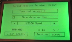
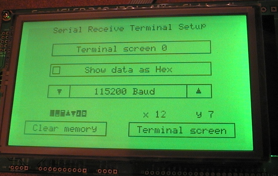
The setup screen is shown above. Here you select the baudrate, and which screen
of 640 ascii data characters you want to view (as the total recording storage
of 2560 bytes is 4 screens of 640 bytes each). At the bottom of the screen are
buttons to clear the data storage memory and to switch back to the terminal screen.
It could be made more pretty but this gives enough functionality for me to use this
as a piece of test equipment. The screen also shows the 7 custom text characters
and the touchpanel X Y coords, these are turned on for development but can be
turned off easily in the code (see the comments).
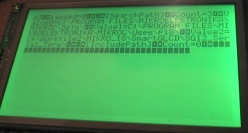
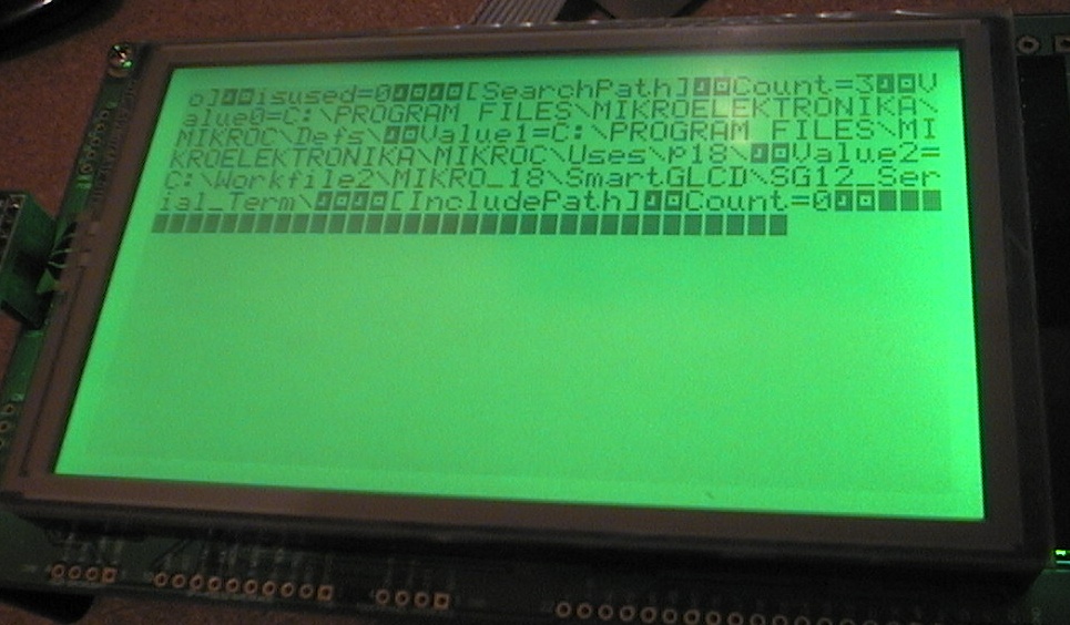
The screen above shows some serial data (sent from a text file) and it is shown
as ascii characters. You can see the carriage return/line feed pair of bytes shown
as custom text characters and some NULL (zero) characters added at the end
of the file, caused by me unplugging the USBserial adapter.
This screenshot gives you an idea of the amount of data that can be shown
on the SmartGLCD in 40x16 text mode.
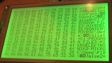
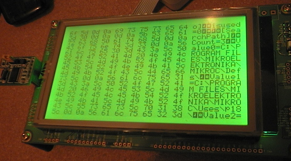
Above shows the same data but displayed as hex/ascii. I copied the format
of many old Dos editors etc that show the hex data on the left and the same
data as ascii in the right column. It displays 10 characters per line, so
in this mode you can only display 160 characters on a screen. You could
easily add some scrolling features etc, just by making some additions to
the source code. This hex/ascii mode is quite useful for examining received
serial data.
This is a large project and the source code is a little untidy. But it works
well and is a powerful tool for displaying serial data, even with large streams
like a GPS NEMA output which is usually a few hundred bytes in total, remember
this project will store and display a massive 2560 received bytes!
Note! A useful feature to add would be an auto start/stop mode, so that after a memory
clear it will not start recording serial bytes until there has been a pause in
sending, then it will automatically stop on the next pause, so that all bytes
between the 2 puases are recorded. I have used this system before for recording
repeated data like GPS NEMA streams. However I have not included auto start/stop
in this project as you can add it easily enough if you wish.
Note 2! The MikroC Usart functions are very easy to use, and are used in this project.
However for the 8MHz xtal they only allow baudrates from 2400 to 115200. If you manually
configure the PIC usart baudrate generator settings you can get much lower baudrates.
Download SG12_Serial_Term.zip
Tut13 - Sinewave DTMF generator
New - 21st Feb 2011
This uses a DDS algorithm to generate 2 simultaneous sinewaves of
precise frequencies for DTMF telephone tone generation. Although my code
can make good precise sinewaves even on a small PIC 12F or 16F I had the
SmartGLCD handy so I did it on that. :)
If you want to see how the algorithm allows multiple simultaneous
sinewaves of precise frequencies to to generated please check out my
zero-error timing algorithms page.
One sinewave table is used to generate all sinewave frequencies. This table
must be a binary size, I used a size of 64 tables entries (see source code).
The algorithm loads the sine table into the PIC PWM module (CCPR2) with
a mathematically exact timing so it can generate any sinewave frequency with
high precision. In this project it generates 2 simultaneous sinewaves of
different frequencies to make any of the 16 DTMF "tones".
The 2 generated sinewaves are added together, and loaded into a single PWM
module so the one PIC output pin generates the DTMF waveform.
The PWM module runs at 62 kHz, so it is easily filtered with a resistor and
capacitor to make the Dual Tone Multi Frequency waveform required by
telephone systems.
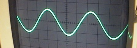

Above you can see the flawless looking 697 Hz sinewave, which tested as 697.00 Hz
on my frequency meter. This was generated with a single BDA 24bit process.
On the right you can see the DTMF output of 2 independent sinewaves 697 Hz and
1209 Hz, both generated by 2 BDA processes and 1 PIC PWM output pin.
This looks textbook perfect, I'm very pleased with the quality of this dual
independent precise sinewave DTMF tone that only required one PIC PWM pin.
(Note; I have tweaked the horiz scale on the 'scope for better viewing).
(code below is an updated example; 6 Mar 2011, it is "twist compenstaed" to
better match telephone system specs.
  // 24bit DDS algorithm for dual simultaneous sinewaves on one PWM module
  // this is an example for DTMF generation
  // 8 MHz xtal (8 MIPS on PIC 18F PLL)
  #define Frow0 46775   // 697 Hz  DTMF rows
  #define Frow1 51674   // 770 Hz
  #define Frow2 57177   // 852 Hz
  #define Frow3 63149   // 941 Hz
  #define Fcol0 81135   // 1209 Hz  DTMF columns
  #define Fcol1 89657   // 1336 Hz
  #define Fcol2 99120   // 1477 Hz
  #define Fcol3 109589  // 1633 Hz
  unsigned long waveA   absolute 0x15;   // 32bit accumulator for the sinewaves
  unsigned char waveA_2 absolute 0x17;   // overload for fast access to byte 2
  unsigned long waveB   absolute 0x19;
  unsigned char waveB_2 absolute 0x1B;
  unsigned char pwm;

  // This uses dual sinewaves of 28% different amplitudes, to match the spec for "twist" in
  // telephone DTMF to ensure the higher freq has a higher amplitude, to cope with line losses.
  const unsigned char sine64low[64] = {
  39,42,46,50,53,57,60,63,66,68,71,72,74,75,76,77,77,77,76,75,74,72,71,68,66,63,60,57,53,50,46,42
  39,35,31,27,24,20,17,14,11,9,6,5,3,2,1,0,0,0,1,2,3,5,6,9,11,14,17,20,24,27,31,35};
  const unsigned char sine64high[64] = {
  50,54,59,64,68,73,77,81,85,88,91,93,95,97,98,99,99,99,98,97,95,93,91,88,85,81,77,73,68,64,59,54,
  50,45,40,35,31,26,22,18,14,11,8,6,4,2,1,0,0,0,1,2,4,6,8,11,14,18,22,26,31,35,40,45};

  // loop and generate dual sinewave DTMF tone
  PR2 = (128-1);            // PWM at period = 128
  while(1)
  {
    while(!PIR1.TMR2IF);  // sync to start of PWM cycle
    PIR1.TMR2IF = 0;

    // calc the A sinewave,
    waveA += Frow0;               // zero error Accumulation
    pwm = sine64low[waveA_2 & 0x3F]; // Binary Divide output (/65536) and keep 6 bits
    // calc the B sinewave, and ADD the 2 waves together
    waveB += Fcol0;
    pwm += sine64high[waveB_2 & 0x3F];
    pwm = (pwm >> 1);   // scale 0-200 back to 0-100 for PWM
    CCPR2L = pwm;       // load added sinewaves into PWM module
  }
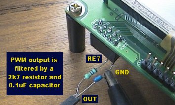
Above shows all the hardware that is required, a single PIC PWM output pin (PORTE.F7) a
2k7 resistor, and a 0.1uF cap.

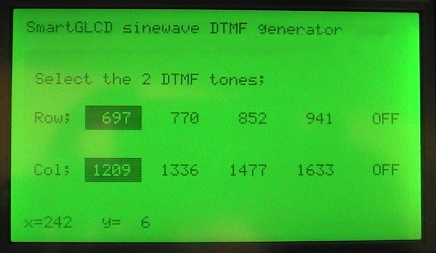
This keypad above shows the way the 2 frequencies are used to represent telephone data.
The right column (col = 1633 Hz) is thought not to be used in telephone
exchange systems.
An important modification I made to my SMartGLCD was to replace the
8 Mhz ceramic resonator with a 8 MHz xtal. The resonator on the SmartGLCD
was ok for most jobs but measured 0.4% fast, and has now been replaced with
a crystal that was tested at less than 30 PPM (parts per million) error.
Now it can be used for reasonably precise frequency generation.
This was a very easy modification to make.

You just press the screen to select the DTMF frequencies. You can also
turn either freq off to check the other freq is a sinewave and check its
frequency is accurate. You may find a tiny percentage error on all the
frequencies, this is because your SmartGLCD has the ceramic resonator
installed, changing to a 8MHz xtal will fix this. Full source code and HEX file
etc provided below.
Download SG13_DTMF.zip
I plan to add more tutorials and SmartGLCD projects at a later date as time
allows.
- end -
[Back to Home Page]