To summarise, it is extremely quick and easy to subtract the 256 ticks for every timer0 overflow, and it is extremely quick and easy to ADD the 24-bit value for the next timed period.
PIC assembler source code!
This first source code generates a 1 second event from a PIC with 4MHz crystal and the timer0 overflow interrupt. This is the code that is easiest to use for most designs.
PIC assembler source code using timer0 interrupt (11 kb)
This next source code generates a 1 second event from a PIC with 4MHz crystal and timer0, but does not require an interrupt so it will still work with the cheapest PICs, or for designs where you choose not to use the interrupt.
PIC assembler source code using NO interrupts! (11 kb)
Note! You can use the 2 code examples above on any PIC and with any crystal. Just adjust the 24-bit period value bres_ to the number of timer0 ticks per second and it will generate a 1 second period. You can also generate longer or shorter periods than 1 second simply by changing that value.
Making a 1 second period using C code
This system will work on a PIC or any micro that has a timer and can use C source code. This does the same thing as the assembler code above.
C code for a 1 second period with a 1MHz timer (4MHz xtal);
	// uses 1 variable; unsigned long bres
	// gets here every TMR0 int (every 256 ticks)

	bres += 256;	// add 256 ticks to bresenham total

	if(bres >= 1000000)	// if reached 1 second!
	{
		bres -= 1000000;	// subtract 1 second, retain error
		do_1sec_event();	// update clock, etc
	}
C code for a 1 second period with a 5MHz timer (20MHz xtal);
	// uses 1 variable; unsigned long bres
	// gets here every TMR0 int (every 256 ticks)

	bres += 256;	// add 256 ticks to bresenham total

	if(bres >= 5000000)	// if reached 1 second!
	{
		bres -= 5000000;	// subtract 1 second, retain error
		do_1sec_event();	// update clock, etc
	}
C code for a 1 second period with a funky 12.391 MHz junkbox xtal);
	// uses 1 variable; unsigned long bres
	// gets here every TMR0 int (every 1024 xtal ticks)

	bres += 1024;	// add 1024 xtal ticks to bresenham total

	if(bres >= 12391000)	// if reached 1 second!
	{
		bres -= 12391000;	// subtract 1 second, retain error
		do_1sec_event();	// update clock, etc
	}
C code for a 1 second period with a 16bit timer1 at 1MHz (4MHz xtal);
	// uses 1 variable; unsigned long bres
	// gets here every TMR1 16bit int (every 65536 ticks)

	bres += 65536;	// add 65536 ticks to bresenham total

	if(bres >= 1000000)	// if reached 1 second!
	{
		bres -= 1000000;	// subtract 1 second, retain error
		do_1sec_event();	// update clock, etc
	}
Special C code examples
This next one is similar to the 1 second generators above. However it is optimised for speed and code space, because it uses a 16bit unsigned int variable for bres instead of a 32bit unsigned long. We do this by using values for the int period and the 1second period that are in the same ratio to each other, but smaller! We divide both values by 16;
Optimised C code for a 1 second period with a 1MHz timer (4MHz xtal);
	// uses 1 variable; unsigned int bres
	// gets here every TMR0 int (every 256 ticks)

	bres += 16;	// add (256/16) ticks to bresenham total

	if(bres >= 62500)	// if reached (1000000/16) 1 second!
	{
		bres -= 62500;	// subtract 1 second, retain error
		do_1sec_event();	// update clock, etc
	}
The next one was for my master LED clock for my home automation system. It uses a Dallas DS32KHz temperature compensated high accuracy oscillator module. But I need to display hundredths of seconds on my nice 12digit LED display, and the oscillator produces 32768 pulses/second, so a hundredth of a second is 327.68 pulses... Ouch!
Fortunately it is easy to make hundredths of seconds (with zero error) from 32768Hz using a bresenham algorithm. I just test TMR1 bit3 in another interrupt, and check for anytime TMR1L.F3 toggles, which occurs 2048 times each second. This next math may not be immediately obvious but if we have an event every 1/2048th of a second, and add 100 every event, then after 1 second we have a total of 204800. So now it becomes obvious that every 1/100th of a second that value grows by 2048. See below;
Generating hundredths of seconds from a Dallas 32768Hz oscillator;
	// uses 1 variable; unsigned int bres
	// TMR1 runs at 32768Hz, from external osc
	// gets here every TMR1 bit3 toggle, is 1/2048th second

	bres += 100;	// add 100 to bresenham total

	if(bres >= 2048)	// if reached 1/100th of a second!
	{
		bres -= 2048;	// subtract 1/100th of a second, retain error
		do_100th_event();	// update clock, etc
	}
The next example was to allow generating of 100th second period from a incoming frequency of 120Hz from the US mains voltage. I wrote this code for someone who wanted to build my 12 digit LED clock with hundredths of seconds and have it synchronised to the US mains for timekeeping accuracy. In Australia the mains is 50Hz, so that is easy. But for "frequency impaired" people in the USA they can use this code to get 100Hz events from the rectified mains signal at 120Hz;
Generating hundredths of seconds from US mains 120Hz freq;
	// uses 1 variable; unsigned char bres
	// gets here every 120Hz, synced to US mains freq

	bres += 100;	// add 100 to bresenham total

	if(bres >= 120)		// if reached 1/100th of a second!
	{
		bres -= 120;	// subtract 1/100th of a second, retain error
		do_100th_event();	// update clock, etc
	}
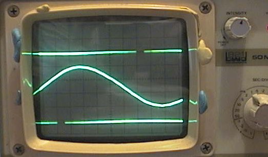
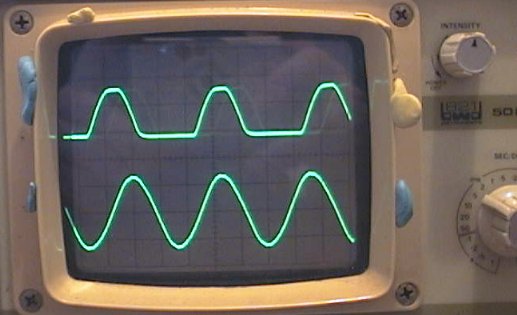
With this specific example the per-unit jitter is quite large, the max jitter error is 1/120th of a second (see below). However the clock will still keep perfect time, it is only the "hundredths" digit that will be affected and that is too fast to read anyway. The overall visual effect of the clock displaying hundredths and tenths of a second is maintained.
Advanced bresenham timing techniques
Clock xtal super-fine calibration.
The int period and 1second period value can both be multiplied by the same number, giving an increase in the timer resolution much greater than the original resolution of the xtal value in Hz.
This next example uses a PIC with 1Mhz xtal, and testing against a GPS receiver over a month shows the PIC clock is 9 seconds fast. So the 1second correction value is calculated as;
(1month+9secs) / 1month which in seconds is; 2678409 / 2678400
Which is 1.0000033602
Multiply by 1Mhz to give the correct 1 second period; = 1000003.3602 ticks
Since we are using an unsigned long variable for the bresenham accumulator the same code will take a value up to 4.29 billion with no issues. So we just multiply both the periods by 1000, which gives 1000 times finer resolution to calibrate the clock but still uses the same simple C code;
C code for PIC 1Mhz xtal super-fine calibration
	// uses 1 variable; unsigned long bres
	// gets here every TMR0 int (every 256 ticks)

	bres += 256000;		// add (256*1000) ticks to bresenham total

	if(bres >= 1000003360)	// if reached 1 second!
	{
		bres -= 1000003360;	// subtract 1 second, retain error
		do_1sec_event();	// update clock, etc
	}
Generating a higher input frequency to reduce jitter
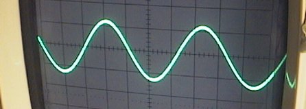
This is an advanced technique to reduce jitter where the two periods are similar or where the output frequency is higher than the input frequency. It works better at low frequencies and requires the input frequency to be fixed and known. This is ideal to fix the type of jitter seen in the 120Hz -> 100Hz picture above.
It generates 1200Hz from the 120Hz input, by generating 10 "fake" events from each real 120Hz input event. Then the bresenham system generates the 100Hz output frequency from the "fake" 1200Hz frequency. This reduces jitter by a factor of 10.
C code for low-jitter generation of 100Hz from 120Hz mains
	// PIC code, 4MHz xtal, TMR1 at 1:8 prescale
	// uses 2 variables;
	//   unsigned int bres
	//   unsigned char pulse

	start:

	// wait here for 120Hz pulse
	while(!check_120Hz());

	// now generate 10 "fake" pulses, each is "1200Hz"
	// which is 833uS. PIC 1Mhz xtal, TMR1 1:8 prescale,
	// we use TMR1L period of 104 = 832uS
	// note! TMR1L loop is also another zero-error system
	// that we keep subtracting 104 from while retaining
	// its internal error.

	pulse = 10;		// make 10 "fake" pulses
	TMR1L = (256-104);	// prep first 1/1200th sec delay

	while(pulse)
	{
		// wait here for fake 1200Hz pulse
		while(TMR1L.F7);

		// now fix TMR1L and do the main bres event
		TMR1L -= 104;	// subtract 1/1200th of a second

		bres += 100;
		if(bres >= 1200)	// if 100th sec reached!
		{
			bres -= 1200;
			do_100th_event();	// update clock, etc
		}

		// subract a pulse, see if 10 done yet
		pulse--;
	}

	// gets here after 10 "fake" 1200Hz pulses,
	// need to detect a real 120Hz pulse, then
	// do it all again!

	goto start;
The code above behaves much like a digital PLL (Phase Locked Loop) in that it MUST generate 10 pulses for very real input pulse (zero cumulative error) and the output is generated from that, again with zero cumulative error.
The two advanced techniques above can be used to provide very fine adjustment of virtually any periods or frequencies.
ZEZJ algorithm - Zero-Error and Zero-Jitter New 21 Nov 2009.
This new algorithm is an adaptation of my zero-error system, that again uses one easy constant to generate any period from any xtal. It also cancels any timer error with every new TMR0 interrupt. However this system is more sophisticated in that it also has zero jitter. This makes it ideal for generating exact frequencies, like a precise 1 second xtal locked output or an exact zero-jitter 50Hz reference or 1kHz reference etc.
Zero Error Zero Jitter algorithm;