[Back to SMPS Page]
[Back to Home Page]
www.RomanBlack.com
PIC-SMPS
How to use a PIC as a complete SMPS!
Roman Black - 8th Jan 2010
What is it?
These are some experiments to use a PIC as a complete SMPS.
As a PIC has everything needed; push-pull FET output pins and the ability to
oscillate, and to measure and regulate voltage and current it might be
possible to use a PIC as a complete SwitchMode Power Supply.
How it works
If the PIC output pin is oscillated at a high enough frequency into an
inductor it performs exactly as a SMPS Buck regulator with synchonous
rectification. Basically that means it will convert +5v to a lower voltage
with quite high efficiency.
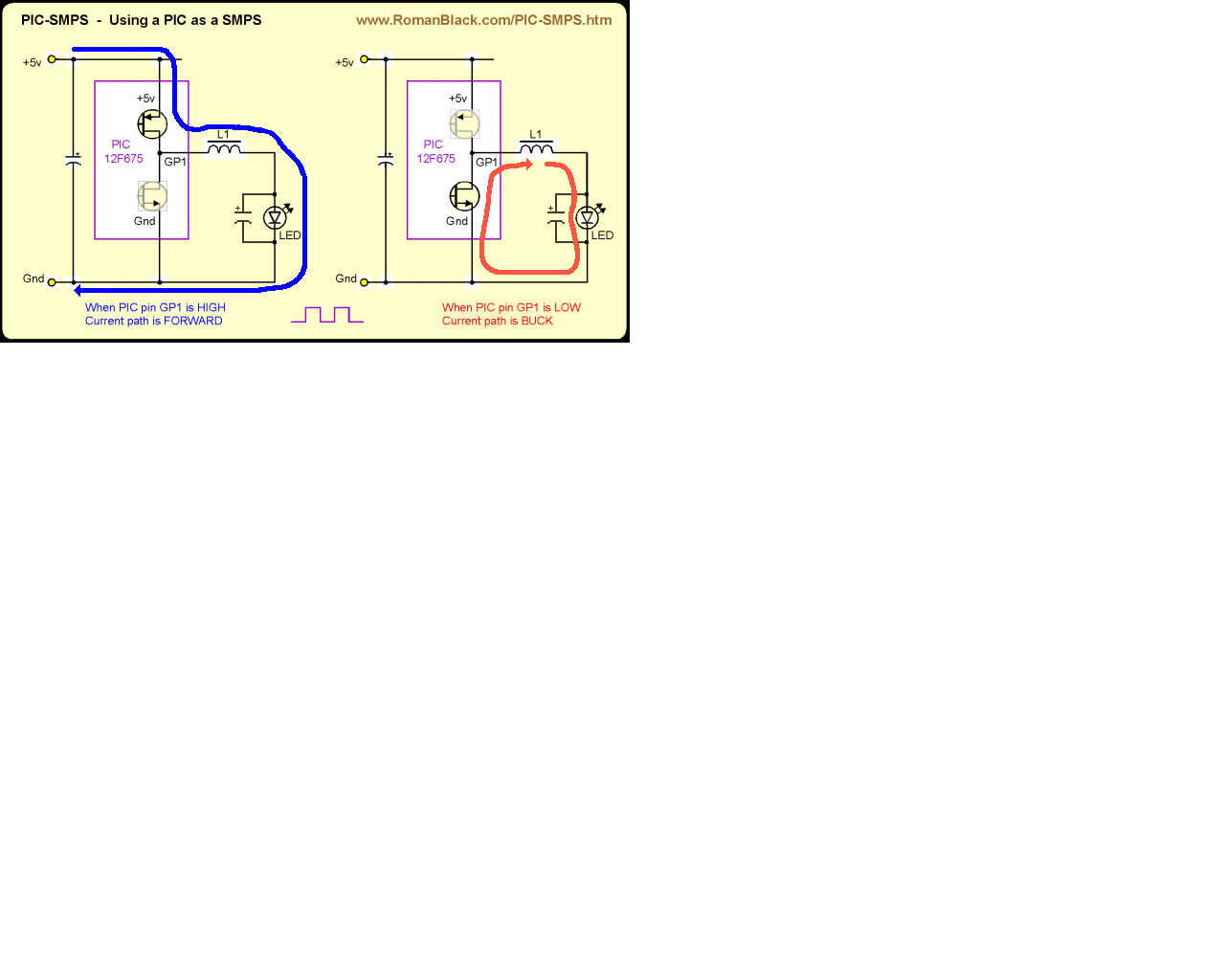
That term synchonous rectification just means that the bottom FET in
the push-pull driver will be turned on during the buck part of the cycle
and it will do the same job that the rectifier diode does in a Buck SMPS.
Synchonous rectification is actually more efficient than a diode, so many
of the new SMPS ICs use this system. Fortunately for us it also means the
PIC does not need an external diode, the only thing needed is a PIC and
an inductor!
Initial testing
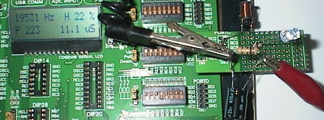
This test setup was used to drive the LEDs from the PIC 16F887 pin RC2
(PWM output pin) as a Buck SMPS. A 1 ohm resistor with a 470uF cap
was used to measure the average LED current. The PIC PWM module was
driven with one of my EasyPIC6 projects that displays the duty cycle
and other PWM stuff;
see here for the PWM generator.
Note! I changed the PIC xtal to 20 MHz and changed the xtal constant in
the code so the PWM operated at 19531 Hz.
The basic tests used a fixed frequency of 19.5kHz and only a single PIC
pin to drive the LED and no cap on the LED. This worked ok, showing most
LEDs would work at reasonable brightness with a 470uH inductor and only
a few % duty cycle. A duty cycle of 10% or more resulted in a very bright
LED.
PIC as a Buck LED driver
For a proper test I used a PIC 12F675 and connected all 5 of its output
pins together. See the schematic below, although there are 5 pins
connected to the inductor, not just 1.
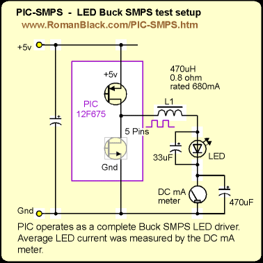
The picture above shows the simplest PIC-SMPS system. The PIC is powered
from regulated +5v and the duty cycle of the oscillation determines the
current through the load (which in this case is a LED).
Since the duty cycle is controlled by the PIC source code this provides
a fixed constant LED current.
I did some quick tests of driving a 20000 mCd 5mm white LED;
Test 1 (49kHz, duty cycle tweaked so LED current = 10mA)
 Vin = 5.12v	Iin = 7.3mA
 Vout = 3.006v	Iout = 9.8mA
 (total efficiency 78.8%)

Test 2 (60kHz, duty cycle tweaked so LED current = 13mA)
 Vin = 5.15v	Iin = 9.6mA
 Vout = 3.083v	Iout = 12.8mA
 (total efficiency 79.8%)

Test 3 (53kHz, duty cycle tweaked so LED current = 17mA)
 Vin = 5.06v	Iin = 12.5mA
 Vout = 3.185v	Iout = 17.2mA
 (total efficiency 86.6%)
I did quite a few tests of different LED currents and frequencies,
the above 3 tests give you some idea. Because of the 1.1mA PIC quiescent
current (even with no LED) the efficiency gets higher with slightly larger
currents.
The actual Buck conversion efficiency is excellent, even though the
PIC FETs have a highish Rds_on resistance. In Test 3 if you subtract
the 1.1mA PIC quiescent current the Buck efficiency is;
Test 3 (subtracting 1.1mA PIC quiescent current)
 Vin = 5.06v	Iin = 11.4mA
 Vout = 3.185v	Iout = 17.2mA
 (Buck conversion efficiency 94.8%)
The PIC 12F675 FET "on resistance" values measured about 3 times better
than the "worst case" values shown in the electrical spec section of
the PIC datasheet. In the examples above I was running 5 PIC output
pins in parallel to reduce the FET resistance further. My testing was
casual and just used common multimeters etc for the measurements
but they are probably within a couple of percent.
I did have a few problems with occasional latchup when the PIC started up,
this was improved a bit by disconnecting the MCLR pin from the oscillating 5
output pins. Also adding a soft start delay to let the PSU and PIC cap
voltage stabilise for a while before starting to oscillate all its pins
seemed to fix it. The best system would probably be to let the voltage
stabilise, then increase the duty over a short time (0.25 seconds?)
to ramp the output voltage up to the final value.
I didn't try larger current loads, technically it should be ok as each
PIC pin is specced for 25mA and the entire PIC port for 125mA. Large
currents like 100mA should be no problem with appropriate ramp-up time.
Also I should say that 5.0v in and 3.2v out (seen above) is not the greatest
conversion range for a buck converter.
If it used a red LED that runs at 1.8v the current gain would be much better
and the overall conversion efficiency would be greater too, being best at
just below 50% duty.
PIC as a Buck regulator 5v to 3.3v converter
With 3.3v devices becoming more common in hobby use and 3.3v SMPS regulator
ICs not always within arms reach I tried using a PIC as a crude 3.3v
Buck SMPS "regulator". The 3.3v regulation is based on the regulated 5v input
so it should be pretty good, apart from some sag at larger currents caused
by resistance of the PIC FETs and inductor.
Du to the slight voltage sag this is NOT a good enough regulator for 3.3v
devices that need to do analog readings etc but in a pinch it should be
fine for peripherals like memory chips, SD cards, anything that uses low
current and doesn't need perfect regulation.
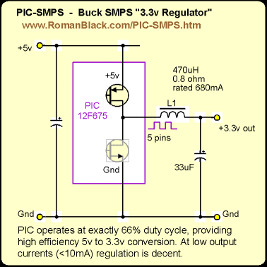
The PIC code ran at approx 1.1MHz and set the output pins HIGH
for 10 PIC instructions and then LOW for 5 PIC instructions (66.7% duty);
  osc_loop:
    MOVLW	0xFF;
    MOVWF	GPIO;
    goto $+1;
    goto $+1;
    goto $+1;
    goto $+1;

    MOVLW	0x00;
    MOVWF	GPIO;
    nop;
    goto osc_loop;
Output voltage regulation (Vin at 5.00v, freq 74.9kHz);
 Iout		Vout
 0mA		3.34v
 1mA		3.31v
 5mA		3.25v
 10mA		3.23v
 20mA		3.13v
 30mA		3.02v
 40mA		2.90v
Current IN vs current OUT;
 Iin		Iout
 1.1mA		0mA
 1.7mA		1mA
 4.5mA		5mA	(72% efficiency)
 7.6mA		10mA	(85% efficiency)
 14.0mA		20mA	(89% efficiency)
This "regulator" seems to work quite well apart from the obvious voltage
sag at higher currents.
For the cost of any cheap 10F or 12F PIC and a single inductor this looks like
a usable 3.3v regulator, provided of course you don't need precise 3.3v
for analog sensors etc.
Future enhancements
(These next ideas seem valid but have NOT been tested in hardware.)
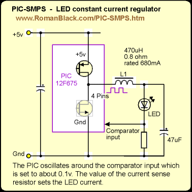
If a low value resistor is placed in series with the LED it can be used
for LED current sensing. Then the PIC comparator (PIC 12F629 or 12F675)
can be set to a low voltage (about 0.1v) and the PIC programmed to
oscillate about this point.
The result below is a LED constant current Buck driver that should work ok
provided the input voltage is regulated.
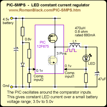
This next idea uses a diode and 3 resistors to create a crude 0.1v reference
for the comparator (instead of the internal reference). This way the LED
current will remain constant even when the input voltage changes, through a
small voltage range at least;
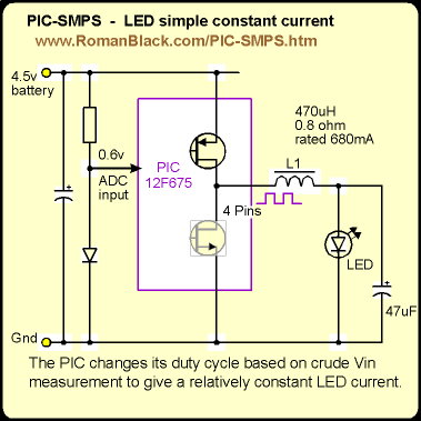
This one below uses a simple open-loop system to keep LED current relatively
constant. It uses the PIC 12F675 ADC to compare the ADC voltage from the diode
against the internal Vref (set by the battery). This uses a simple lookup
table in code to set the duty cycle. The current regulation will not be as
good as the two closed-loop examples above but it should be fine for things
like torches or emergency lights. It's main advantage over the circuit above
is the lower parts count and it has 4 output pins, not 3.
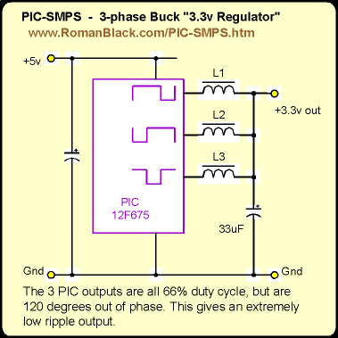
This next one is a bit gimmicky but may be fun to play with. It is another
5v to 3.3v converter but this one uses 3 inductors and each is driven from a
66.7% duty cycle that is 120 degrees out of phase with the others.
This means that at any point in time the cap is driven with 2 HIGH levels
and one LOW level.
I don't know if there is any real practical value to the circuit but it
should offer extremely low ripple voltage output, and the general idea
amused me. At least it is still low parts count. :)
- end -
[Back to Home Page]