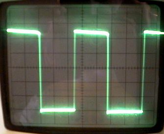
[Back to Home Page]

www.RomanBlack.com

The 2-transistor Black regulator
Very cheap high-performance switchmode +5v regulator
Roman Black - Aug 2006 (orig Nov 2001 and Sept 2002)


What is it?

This is a 2-transistor circuit that can be used to replace a +5v regulator or a +12v regulator etc.

It can provide 12v to 5v conversion, 24v to 12v conversion (or other voltages). It is a switchmode regulator which means that it is very efficient at converting the voltages, and will use a lot less input current to provide the same output current. In many portable applications it can be a much better choice than a 7805 +5v regulator normally used by hobbyists.


How it works

The 2-transistor Black regulator evolved over a 12 month period from an original 2-transistor smps circuit designed by Richard Ottosen.

I did the main re-design in September 2002, with the goal of reducing parts count to an absolute minimum in number and pricing, while also attempting to get switching efficiency and regulation as good as many smps chips. The results were quite good.


This is the main switching waveform with the Black regulator running at 93.1% efficiency. The vertical switching times are so fast the cro needed to have its brightness turned right up.

The circuit is a 2-transistor BUCK oscillator that oscillates around the properties of the inductor L1. Smps buck circuits store switching energy in the magnetic field of the inductor.

It is very efficient for these reasons;
  • Very fast switching times
  • Very low saturation voltage on the main switch Q1
  • Almost all the current used by the circuit goes to the output in one way or another
  • Capacitors provide a "timed off period" in a monostable fashion, similar to smps chips


    Cycle of operation


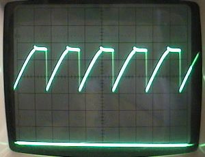
    The 4 phases of the cycle can be seen in the wavform above;
    (Voltage waveform at point Z (Zener voltage) 1 div = 1v)
  • The flat part at the top is the ON phase (zener =5.6v)
  • The sharp drop from 5.6v to 3v is the TURN OFF phase
  • The ramp is the OFF (timed monostable delay) phase
  • The tiny nipple at the top is the short TURN ON phase


    Advantages of the Black regulator

  • Parts cost is very low, 2 cheap transistors instead of a smps chip
  • Very high efficiency (equal to or better than many smps chips)
  • Good regulation
  • Common ground design (3-pin regulator, can replace a 7805)
  • Works great with a wide inductor range (ie any cheap surplus inductor)
  • Wide flat powerband (area of max efficiency)
  • Takes high input voltages (higher than a 7805 and most smps chips)
  • Good immunity to noise on input or output
  • All parts are common (no hard to get chips)


    Pre-tested Black regulator circuits;

    Each of these following circuits has been pre-tested and optimised. All include circuit, parts list, parts costs, photo, test results, charts. Parts costs are at low-volume prices.

    +5v output Black regulator - Low Cost

    +5v output Black regulator - Good Regulation

    +5v output Black regulator - Good All-Round

    +12v output Black regulator - High Efficiency

    +12v output Black regulator - High Efficiency + Current Limited

    Also; my +5v to +12v step-up converter HERE

    NEW!!! SMPS high efficiency drivers for high-power white LEDs

    NEW!!! Using a single PIC as a SMPS

    NEW!!! 12 Dec 2011 - A 3-transistor NEGATIVE voltage generator


    High voltage use

    I have had some inquiries re using the Black regulator for high voltages, ie 40v up to maybe 120v or so. High voltage input is one area where this circuit can really beat the dedicated smps chips (or 78xx regulator chips) as these chips rarely accept input voltages over 30v or 40v.

    If you want to use the Black regulator for high voltage circuits I suggest the following:
  • Make sure Vce of Q1 and Q2 is rated 50% higher than input voltage
  • Use a darlington for Q1, so you can use a high value resistor for R2 to keep R2 dissipation low
  • D1 must be Vr rated at 50% higher than input voltage, a schottky probably won't do. Try a 1N4937; 600v 1A fast switching diode
  • Increase RZ resistance
  • Reduce C1 and C2 as RZ was increased
  • A resistor in series with C2 may be needed
  • Retuning of the C1:C2 ratio will be needed, use a much smaller C2
  • R2 and RZ may need to be 0.5w or 1w types - check heat
  • Use a fuse on circuit input!


    Simple Dummy Load

    This is a simple dummy load that gives almost constant-current performance. It took about a minute to solder together and made an excellent adjustable dummy load for testing the circuits up to about 300mA. Use a 4.7 ohm 5w resistor if you need a load up to 700mA, I just soldered a 10 ohm resistor across the other resistor to give both ranges. Any big NPN transistor should work.


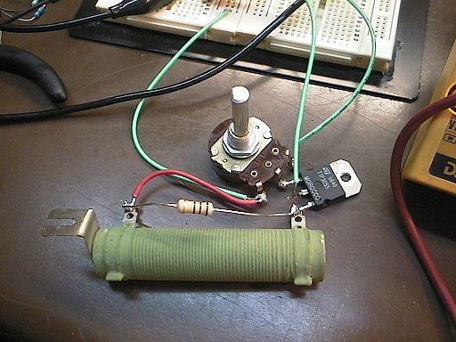
    Variable constant current dummy load;
    (requires +5v regulated supply also).
    
    Black
    regulator
    Output   ------------,
                         |
                         |
    +5v  --------,       |
                 |       |
                 |       |  NPN
       500 ohm   R       C  TIP3055
          pot    R<----B    10A 80v
                 R       E
                 |       |
                 |       |
                 |       Rload   8.2 ohms  5w
                 |       |     (or 4.7 ohms  5w)
                 |       |
    Gnd ---------*-------*--


    - end -

    [Back to Home Page]