INSTRUCTIONS;
1. Glue the 3 heater resistors and thermistor to the xtal body with TINY spots of superglue. Glue the thermistor in good contact with the xtal body, and touching the 2 heater resistors on that side of the xtal. Cure the superglue for a few minutes under a warm desk lamp.
2. Glue the transistor (or 2 if you make your own darlington) to the xtal body.
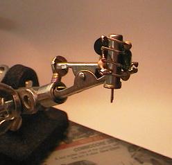
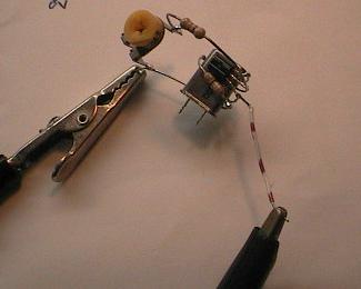
3. Using pointy pliers gently bend the legs to the right position and trim to length for neat construction. Put a small spot of solder on the joins and check with magnifying glass. Above you can see the green thermistor on the right (between the 2 resistors) and the black transistor and 1 resistor on the left.
4. Trim the capacitor leads and solder it across the thermistor.
5. Hook up 2 short power wires; the +5v end of the TOP heater resistor (this is the +5v connection) and the 0v (gnd) is connected to the emitter of the transistor (see schematic).
6. Connect the 100k and 220k trimpot in series (chain) and connect them from +5v to the base of the transistor. See schematic.
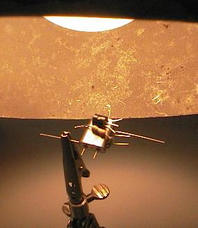
7. Turn the trimpot to centre and connect REGULATED +5v power through a 50 mA ammeter (multimeter on 200 mA range will do).
8. (See above photo - testing and adjusting) Adjust trimpot to about 15mA total current draw. Allow temperature to stabilise (may take 30 seconds) and adjust the trimpot again if needed. The trimpot sets the temperature of the xtal, you can measure it if you have a thermometer (I use an infrared optical thermometer), otherwise 15mA raises the xtal about 8'C above room temperature so you can work from that.
9. Now disconnect power and disconnect the trimpot and measure it, then replace with a fixed resistor to reduce size and make it neater and more reliable.
10. Test it still works with just the fixed resistor, I chose 220k which regulated at about 35'C. Test that it draws less current when warmed by a desk lamp, and draws more current when cooled by a fan. If it all tests ok, shorten all the leads and make it more compact and neat ready to cover with epoxy.
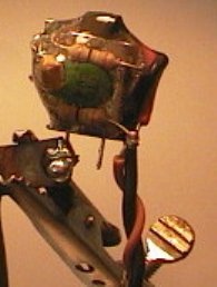
11. Put a thick layer of araldite (5 minute epoxy) all over the whole thing but make sure your 2 (or 3) xtal leads and the 2 power leads come out dry so you can solder to them later! The araldite forms a decent thermal conductor and makes the entire circuit into one thermal mass.
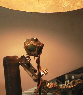
12. Cure the araldite under a desk lamp (see above) at "warm sun" temp (50'C) for half an hour or so. Then test it again and hope you didn't mess it up! You can clearly see above the green thermistor surrounded by 2 heating resistors.
13. Cover the entire xtal oven with generous layer of styrofoam insulation. This reduces its power consumption. Seal any air gaps with more epoxy or silicone etc.
14. Cover with aluminium foil or other RF shield, wrap a ground wire around that and glue in place (optional).
Note! I haven't covered this one with styrofoam yet until I build the clock because I want to check size and clearances etc. I did wrap it in a large loose wad of tissue paper (for testing) and current consumption dropped a few mA as expected. Overall, the xtal oven does seem to work really well! Heating or cooling it performs exactly as expected; the heater current responds appropriately and my infrared thermometer says it remains at 35'C at all times. Success!
Uses for the xtal oven
I built mine for a precision real-time clock for my loungeroom. This circuit will also be handy for anyone building my Binary Clock Kit or building their own clock using my 1-sec PIC timer algorithm.
If you are making your own clock, you will need to calibrate your software to match the new exact xtal frequency. I suggest using a GPS, these display (and serial output) a time code that is locked to the atomic clocks on the GPS satelites. Adjust it once a week and if it gains/loses less than a second a week that will be less than a minute a year error. With a little effort to calibrate it, your xtal oven clock should be accurate to a few seconds a year.
You could also retrofit this circuit to an existing clock, or a test instrument like a frequency meter. Or certain amateur radio (HAM) equipment that needs a stable frequency. All it requires is a +5v regulated supply and 0 - 40 mA, (usually less than 20mA).
Adapting my design for SERIOUS USE
If you need more serious temperature control, especially for outdoor use with large temperature variations, the circuit needs to be improved. I suggest using more current through the heater resistors (reduce their resistance), obviously to cope with lower (MIN) temperatures you need more heater power. Good thermal insulation will help both in performance and to reduce total current needs.
To cope with higher (MAX) temps you need to run the xtal at a higher temp than any temp the device will experience. If it is to run in a car or robot in the hot sun this might be a considerable temperature. Again this may involve increasing the power to the heater resistors.
Finally you might want to switch to a higher precision temperature controller, ie use a 8-pin comparator chip instead of a single transistor! Either way you can expect to do a lot of temperature testing. It might be easier just to buy a commercial OCXO providing it can handle your temp range needs.
So why not just BUY a xtal oven??
Where's the fun in that?? :) And anyway, I built this in about an hour from $1 worth of parts. A commercial OCXO costs a LOT more than that with postage and would have taken a week or more to get here.
My circuit is also more energy efficient than commercial OCXO products and only needs a few mA as it was tailored for my needs (ie low power indoor use within a limited temp range).
And this way I got to pick my own xtal frequency too.
- end -
[Back to Home Page]